0
\$\begingroup\$

This has been driving me insane for some time now. I can't seem to figure out why my LEDs have issues with communication. They have plenty of power supplied. I broke down my entire circuit to the most basic elements:

  • 12 V, 30 A PSU
  • ESP32 with WLED
  • WS2811 LED strings (100 pixels each)

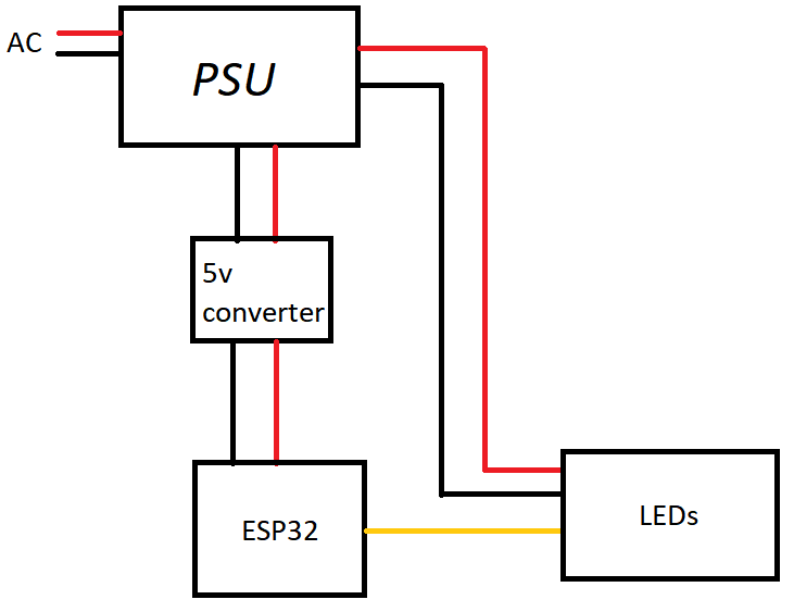
Everything is powered by the one 12 V PSU, the lights are powered separately (not from the microcontroller), I have a step down converter from 12 V to 5 V for the ESP32, everything is soldered/securely connected, I have used both a logic level shifter and signal booster and I have the same issue, no change. The LEDs are connected by ~35 foot long wire, 18AWG.

The LEDs flicker and do not display the right colors or simply don't turn on when connected. Sometimes if I hold the bare wire for the data, the LEDs begin to work pretty much fine, I wouldn't complain if they worked that way. I changed out nearly all components in the circuit including some wires and the microcontroller, and I get the same result. If I resolder the data connection, I get a different result each time. Sometimes it works, sometimes it doesn't. If it's working and I add another LED string to a new pin on the microcontroller, it pretty much all goes to crap again and I end up unsoldering things randomly to get it to work again. Here's a little schematic of the most basic circuit I tried.

enter image description here

I feel like this should really not be as difficult as it is. I implemented a similar project with 5 V lights that were not programmable - I used a single 5 V power source and controlled the lights via a relay instead, and it works just fine. The only thing I haven't been able to try is using a different step-down converter for the ESP32. This is the one I'm currently using.

Any suggestions would be greatly appreciated.

\$\endgroup\$
6
  • \$\begingroup\$ test with shortest wires possible \$\endgroup\$
    – jsotola
    Commented Feb 4, 2023 at 0:00
  • 1
    \$\begingroup\$ Connect 12V and 5V grounds together. \$\endgroup\$
    – user263983
    Commented Feb 4, 2023 at 0:12
  • \$\begingroup\$ Which level shifter? Which signal booster (whatever that even means)? Sending about 1 Mbps of data stream for 35 feet is no easy task. Edit : Ah OK, you are using the TXS0108E, get rid of it immediately. \$\endgroup\$
    – Justme
    Commented Feb 4, 2023 at 0:14
  • \$\begingroup\$ Multiple LED strings? How are they connected exactly to the ESP? You definately need a level shifter. Did you use the 33 Ohm resistors according to tge data sheet? \$\endgroup\$
    – datenheim
    Commented Feb 4, 2023 at 0:42
  • 4
    \$\begingroup\$ Try adding an extra ground wire from the ESP to the LED strip. \$\endgroup\$ Commented Feb 4, 2023 at 1:05

2 Answers 2

1
\$\begingroup\$

WS2811 is a 5V chip that requires 5V logic levels on its digital input pins. To register a solid high it needs 0.7VCC or 3.5V (cf datasheet Vih parameter).

Logic thresholds also depend on temperature and supply voltage so the manufacturers put in some margin to guarantee it'll work reliably. So, on a good day, if you're lucky, it'll kinda work with 3.3V but then it won't.

You can use a 74HCT logic chip as a cheap voltage level translator. When powered from 5V it will reliably read 3V3 logic levels, and output 5V logic levels. Doesn't matter which type, AND, OR, whatever, just wire it as a buffer as long as it's not inverting.

There's also a grounding issue, which is not possible to debug without more info. You should post a picture of the setup. And the wires are probably too long.

\$\endgroup\$
4
  • \$\begingroup\$ Thanks for the info. I have tried using logic level shifters (I have the TXS0108E), but it doesn't seem to change anything. I've also used an F-amp due to the wire length, still the same. The circuit I posted above is exactly how I have it set up. The logic level shifter and F-amp are both as close to the microcontroller and power supply as possible. \$\endgroup\$
    – astraledm
    Commented Feb 4, 2023 at 0:09
  • \$\begingroup\$ Still gonna need pics. Is the 5V DC-DC isolated? Also ESP32 has wifi so why not put it close to the LEDs and use short wires? Voltage drop due to current is going to be substantial \$\endgroup\$
    – bobflux
    Commented Feb 4, 2023 at 7:12
  • \$\begingroup\$ pic - One strand of 250 LEDs initially worked perfectly without a logic shifter and with the 35 or so feet of wire so I just went that route - my end goal was to control about 600 LEDs and I liked it all coming from one controller, just easier logistically. I added a second strand, controlled via another pin on the ESP, to total about 350 LEDs, and that's when I started to have issues. Over the weekend I found 74AHCT chips, I hope those are ok? Didn't seem better. Tried a ground like others suggested as well and no improvement. \$\endgroup\$
    – astraledm
    Commented Feb 6, 2023 at 6:44
  • \$\begingroup\$ I think you have too much voltage across the ground wire due to chopped LED current. Did you put a large electrolytic capacitor at the LED strip? Also the level shifter needs decoupling \$\endgroup\$
    – bobflux
    Commented Feb 6, 2023 at 8:58
0
\$\begingroup\$

The TXS0108E is not a suitable level shifter. At least not for this environment.

Use any 74HCT type chip you can find and try again.

\$\endgroup\$
2
  • 1
    \$\begingroup\$ Thanks, I'll try that one. Could you explain why the TXS is not? \$\endgroup\$
    – astraledm
    Commented Feb 4, 2023 at 0:37
  • \$\begingroup\$ @astraledm It is not meant for long wires which have lots of capacitance and long delays in signal reflections. It's intended for maybe a couple of inches. \$\endgroup\$
    – Justme
    Commented Feb 4, 2023 at 2:40

Your Answer

By clicking “Post Your Answer”, you agree to our terms of service and acknowledge you have read our privacy policy.

Not the answer you're looking for? Browse other questions tagged or ask your own question.