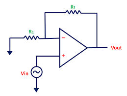
Why is resistor R1 connected to the inverting terminal of the op-amp in a non-inverting op-amp configuration? What will happen if we replace it with a short circuit?
5 Answers
Probably you need to review what negative feedback means to an op-amp, how it makes the op-amp behave, and how it's implemented in your circuit and in a non-inverting setup too. Negative feedback is when a change in the op-amp's output somehow causes its own input to change in a direction that opposes that initial change.
Op-amps have two inputs. On the non-inverting input (with the "+" label), if the potential \$V_{NONINV}\$ there were to rise (while the other inverting input "−" potential \$V_{INV}\$ stays fixed), that will cause the output voltage \$V_{OUT}\$ to rise in potential. On the other hand, if we keep the non-inverting input fixed while we raise the inverting input potential, then the op-amp's output will fall.
In other words, potential changes at the non-inverting input cause output changes in the same direction, but changes to the inverting input cause output changes in the opposite direction.
This is all wrapped up in the simplest relationship \$V_{OUT} = A(V_{NONINV} - V_{INV})\$, where \$A\$ is a large gain (hundreds of thousands, or even millions) which multiplies the difference between the two input potentials. The most important thing to remember is that when \$V_{NONINV}\$ rises with respect to \$V_{INV}\$, then output \$V_{OUT}\$ also rises, but if \$V_{INV}\$ rises with respect to \$V_{NONINV}\$, then \$V_{OUT}\$ will decrease.
It should be clear that to implement negative feedback, wherein when the output changes we want the input to change in such a way that opposes that change, all we need to do is make sure that when \$V_{OUT}\$ rises, either we need to make \$V_{INV}\$ also rise, or we need to make \$V_{NONINV}\$ somehow fall. Either approach would work, but the former (using \$V_{INV}\$) is easier, because we don't need to do any "signal inversion" (flipping upside-down) of any kind.
To understand the effect of negative feedback, a good analogy is steering in a car. If you are in a turn in the road, and you feel you are turning too much, you move the steering wheel in the direction that reduces the rate of turn. If your current rate of turn is too small (you're going too straight), you adjust the wheel in the direction that increases the rate of turn. Another analogy is a room heater, where if the temperature is too high, you reduce heating, and if it's too low, you increase heating. In other words, you always adjust in a direction opposing the current excess or insufficiency. By constantly adjusting in this manner, the result is that you settle at a rate of turn (or rate of heating) exactly right for the desired outcome.
By contrast, if you employed positive feedback (by feeding back to the non-inverting input), where you adjust in a direction which reinforces an erroneous condition, you crash the car, or set fire to the room.
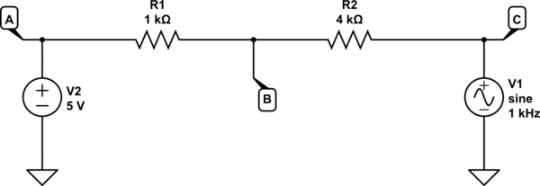
Now it's clear we should feed back some fraction of the current output to the inverting input, and we usually do this with a resistor potential divider, like this:
simulate this circuit – Schematic created using CircuitLab
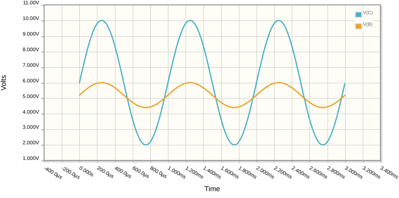
Here I have held node A at a steady +5V, while I force node C to oscillate up and down between +2V and +10V. The potential at B will always be somewhere between A and C (as determined by R1 and R2). Consequently, and hopefully intuitively, you can see that the potential of node B will rise and fall with C, but with a reduced amplitude:
Node B therefore is a perfect candidate for the inverting input of an op-amp, if we connect C to its output; When the op-amp's output rises (C), then so will its inverting input (B), to some degree, thereby implementing negative feedback:
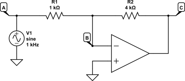
This isn't quite the configuration you showed us, and I'll get to that in a moment. For now, just understand that when C (the op-amp output) rises in potential, so does B (not as much, but it does rise), and since B is the inverting input of the op-amp, a rise in B opposes the initial rise in C that caused it - that's negative feedback.
In the above circuit, my input to the system is node A, where I am injecting an AC signal (source V1), but the potential divider formed by R1 and R2 is still performing that same function of producing a voltage somewhere between \$V_A\$ and \$V_C\$. The most important point to keep in mind here is that when \$V_C\$ rises, so does feedback \$V_B\$.
We can rearrange the circuit slightly, to resemble yours:
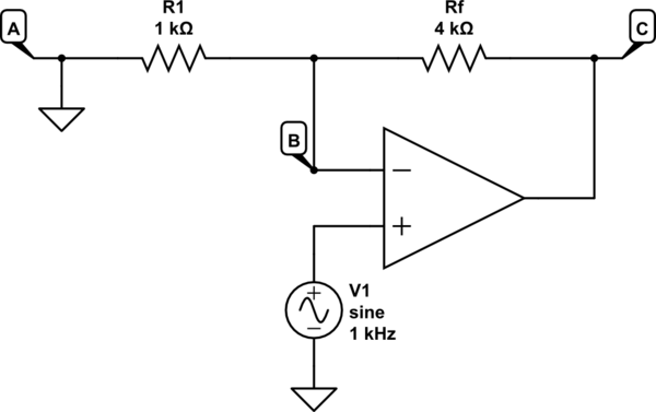
As before, here we are using R1 and Rf to produce a voltage somewhere between \$V_A\$ and \$V_C\$, but this time we are holding A at 0V (\$V_A = 0V)\$, and applying our input signal to the op-amp's non-inverting input.
However, this is still employing negative feedback, since as \$V_C\$ increases, so will the potential \$V_B\$ at the op-amp's inverting input. That behaviour has not changed, and because this is still negative feedback, the system will still settle at some equilibrium. Where that point of equilibrium actually is requires some math to understand, but to address your question, just understand that as long as we make the inverting input change in the same direction as the output, we have negative feedback, and the associated stability.
Lastly, I'll address your question about replacing R1 with a short circuit, like this:
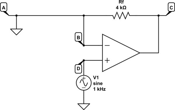
Hopefully, after all I've said above, you can see that there's no longer negative feedback happening here. The op-amp's inverting input B is held at 0V. This means that as C changes potential, B does not. Previously we relied on the behaviour of a potential divider formed by R1 and R2 (or Rf) to apply some fraction of change in \$V_C\$ back to node B, but this cannot happen if B is held at 0V. In the absence of any negative feedback, all that will happen here is:
$$ V_C = A \times (V_D - V_B) $$
You have no control over gain, or bandwidth, or any other behaviour configurable using negative feedback techniques. You just have a very unpredictable, very high gain (\$A\$ is huge, remember), very low bandwdidth amplifier.
Lastly, let me show you what happens when you replace Rf with a short circuit:
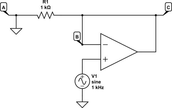
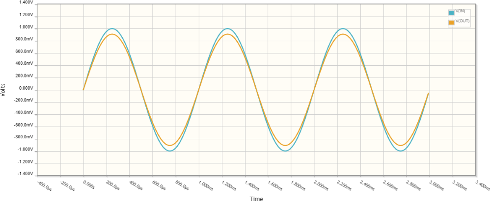
R1 no longer plays a role here, since negative feedback is 100%. In fact you would usually remove R1 altogether in this configuration. Any change at C is fed back to B, in its entirety. With 100% negative feedback, we have unity gain. We also have very high input impedance (remember, the op-amp's input impedances are very, very high) and very low output impedance. This setup is called a voltage follower, and is commonly used to produce a very strong copy of a weak input signal.
Maybe the most important thing
There is a very interesting, and critically important consequence to negative feedback with an op-amp: the op-amp always adjusts its output so that its two inputs are equal in potential. That is, with negative feedback:
$$V_{INV} = V_{NONINV}$$
I won't explain why that is (perhaps you can figure it out intuitively), or how important this is, but it is a huge deal. You'll learn why in your future studies, and I strongly, very very strongly encourage you to remember this, and to do your best to learn why it's so important.
-
\$\begingroup\$ Nice explanation. However, one short remark for a better understanding: The opamp always adjusts its output so that its two inputs are NEARLY equal in potential. The potentials are equal only for the theoretical case of infinite opan loop gain Aol. In reality, there is a very small voltage between both inputs: Vdiff=Vout/Aol (higher µV range or lower mV range). In practice, during calculations we may always ASSUME Vdiff=0 because the resulting error will be much smaller if compared with other neglections/uncertainties (input/output impedances, resistor tolerances)...) \$\endgroup\$– LvWCommented Feb 5, 2023 at 8:18
How do we explain circuits?
To understand a circuit, it is not enough to explain what it does and how it does it; it must also be explained why exactly it does so. Only then can we say that we have truly understood the circuit.
Building a non-inverting amplifier
The best way to explain a circuit is to build and reinvent it. I will do it in a scenario of eight consecutive steps illustrated by CircuitLab simulations. The block diagrams do not work; consider them as pictures.
STEP 1: How do we copy voltage?
A major task in life when we materialize our goals is "copying" - we have some goal X in our head and we want to materialize it as Y = X.
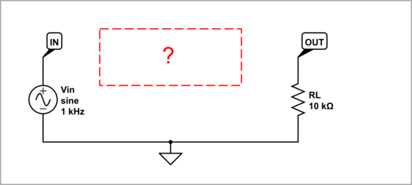
simulate this circuit – Schematic created using CircuitLab
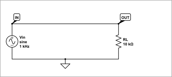
In electronics, such a task is "voltage copying" - we want the same voltage Vout as the input Vin to appear across the load RL.
STEP 2: "Wire follower"
The obvious solution in life is to get down to business and solve the problem ourselves.

In electronics, the first idea that comes to mind is to connect a piece of wire from the source to the load. It would work well if the voltage source was ideal (with zero internal resistance) and the wire was ideal conductor (with zero resistance).
STEP 3: Disturbed "wire follower"
In life, however, something always appears that prevents us from realizing our intentions - for example, we are weak to do it.

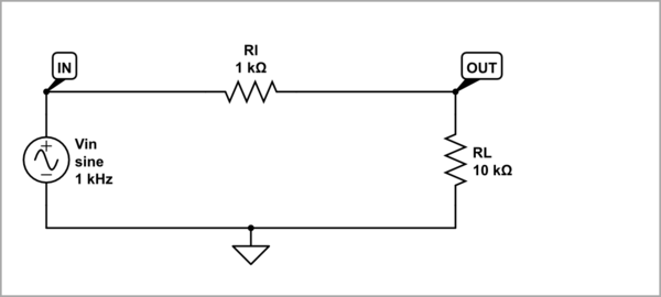
In electronics, we work with real elements that have some resistance (Rl in total). An unwanted voltage drop appears across it, which is subtracted from the input voltage. As a result, the voltage across the load is less than the input voltage.
STEP 4: Negative feedback follower
In life, we solve such problems through the ubiquitous negative feedback principle. In its perfect form, it means making one quantity Y equal to another quantity X by comparing the two quantities by subtraction and varying the quantity Y until the difference X - Y is (almost) zero. In this way we maintain the temperature and lighting in a room, the speed and direction of a car, the state of our mind and body, the level of our voice when speaking and countless other examples... In our example, we can hire workers (become bosses :-) and assign them to do our work.

Since this principle is so powerful, then let's use it to make a perfect voltage follower. First, we supply the load by a separate voltage source (the potentiometer P bipolarly supplied by +V and -V) and adjust its voltage equal to the input voltage. To do this, we decide to take advantage of KVL - we include the two voltages in series and in reverse in a loop and apply their difference to a zero voltage indicator (sensitive voltmeter).
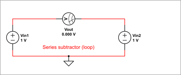
Now we rotate the potentiometer's wiper until the voltmeter shows zero voltage. Thus I adjusted the potentiometer (its wiper position or transfer ratio K < 1) using CircuitLab - I opened the parameter window and watching VM I started to change K until zero the reading.
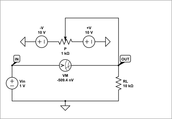
The trick here is that the load draws current from the new source and not from the input source. So no current flows through the zero indicator; as if it has an infinitely high resistance (open circuit). This phenomenon was used as far back as the 19th century to make "ideal" voltmeters. The problem then was that they did not have good voltmeters because they made them using an ammeter and resistor in series, and that is why they came up with this trick. And you can use it now if you need an "ideal" voltmeter and you have a real one. Connect it between the wiper and ground and zero the voltage indicator (a sensitive voltmeter, maybe not a very good one) reading. The effect is striking - you have loaded the input source with a "bad" voltage indicator and a "bad" voltmeter in series... but the source "sees" an infinite resistance (open circuit, "nothing"). For the same purpose - artificially increasing resistance, this technique (aka "bootstrapping") is used today in modern amplifier stages.
STEP 5: Op-amp follower
Now it remains only to automate the circuit through an operational amplifier that performs the role of the potentiometer, the voltmeter and the person. The amplifier must have a differential input because the difference between the two voltages is "floating" (maybe this was one of the reasons to make the op amp with a differential input). The op-amp "observes" the voltage difference across its input and adjusts its output voltage to keep it near zero (the H&H "golden rule"). As a result, Vout = Vin.
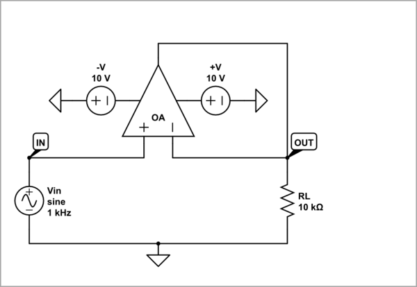
STEP 6: Disturbed op-amp follower
Now remember what we do when in the life situations above some disturbance prevents us from fulfilling our purpose - we begin to compensate for it with extra effort.

Similarly, imagine we put some disturbing resistance Rout in series with the op-amp output (in this way we can mimic its output resistance). The op-amp will sense this intervention through its inverting input and start raising its output voltage Vout1 until it compensates for the disturbing resistance. As a result, the equality is restored, Vout2 = Vin.
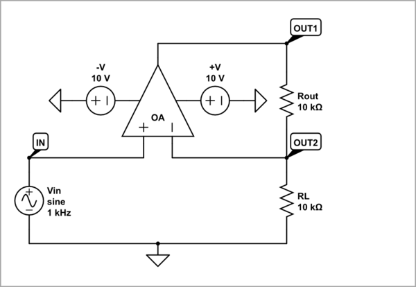
STEP 7: Op-amp non-inverting amplifier
It is a well-known fact that obstacles in life make us stronger; this is for example used by coaches and educators.

To apply this wisdom of life in our electronic circuit, we only need to replace the two resistances RL and Rout with constant resistors R1 and R2 and connect the load to OUT1. The disturbed follower becomes an amplifier.
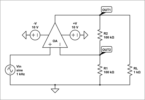
Now let's answer the OP's question:
- R1 = 0. The "disturbance" is infinitely high. In an effort to overcome it, the op-amp output voltage reaches the supply voltage (the op-amp is saturated).
- R2 = 0. There is no disturbance (only R1 is in parallel to the load).
- R1 is removed (open circuit). There is no disturbance (R2 does not play any role if not extremely high).
- R2 is removed (open circuit). The "disturbance" is infinitely high. Striving to overcome it, the op-amp output voltage reaches the supply voltage (saturated).
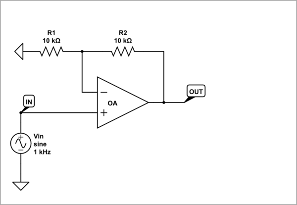
STEP 8: Conventional diagrams
Now that we have already reinvented the circuit of the non-inverting amplifier by building it step by step, let's draw its block and circuit diagrams in the conventional way to make the connection.

Building an inverting amplifier
So far we have "invented" a voltage follower using an op-amp with a differential input. But what if we only have a humble amplifier with a single-ended input? They had such a problem a century ago when they began to apply the principle of negative feedback in electronic (tube) circuits. Also, we made a follower and non-inverting amplifier; but we often need an inverter (K = -1) and an inverting amplifier. What should we do then?
STEP 9: Negative feedback inverter
As above, to make a perfect voltage inverter, we supply the load by a separate voltage source (the potentiometer P bipolarly supplied by +V and -V) and adjust its voltage equal but now with opposite sign to the input voltage. To do it, we remember that with the help of KVL we have already made an extremely simple series voltage subtractor (just a loop). We guess that we can make an extremely simple parallel current sumer through KCL (just a node). Then, we can convert it to a parallel voltage sumer by including resistors R1 and R2 that act as voltage-to-current converters.
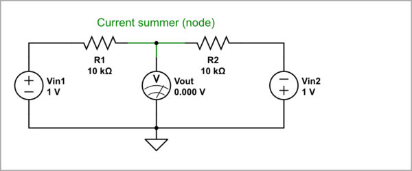
So, we include (through the resistors) the two voltages "in parallel" and in reverse to ground and apply their difference (the midpoint voltage) to a grounded zero voltage indicator (sensitive voltmeter).
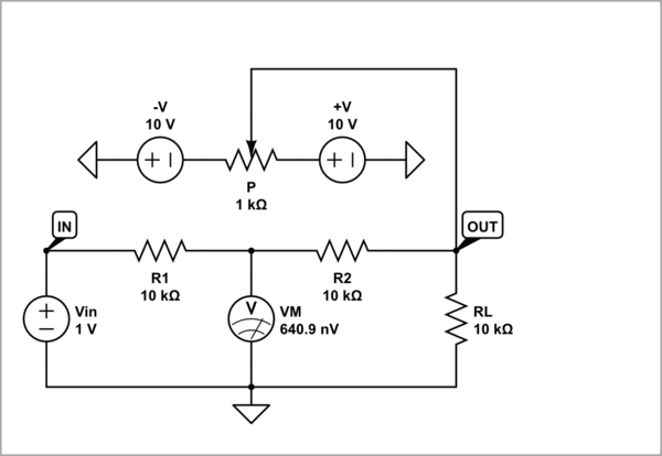
As above, we rotate the potentiometer's wiper until the voltmeter shows zero voltage. Thus I adjusted the potentiometer (its wiper position or transfer ratio K < 1) using CircuitLab - I opened the parameter window and watching VM I started to change K until zero the reading.
Here we see another clever trick - the famous "virtual ground". What the hell is this?
The "potentiometer voltage source" compensates the voltage drop across R2 so that the voltage across the voltmeter is zero. Thus the input voltage source "sees" only R1; R2 is destroed. The current increases - it is Vin/R1 instead Vin/(R1 + R2). This technique is widely used in electronic circuits. For example, we can made an "ideal" ammeter connecting a "bad" ammeter (with high resistance) in the place of R2.
STEP 10: Op-amp inverter
Now it remains only to automate the circuit through an operational amplifier that performs the role of the potentiometer, the voltmeter and the person. The op-amp differential input is not used; so we ground the "needless" non-inverting input.
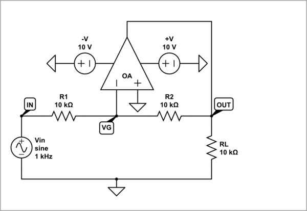
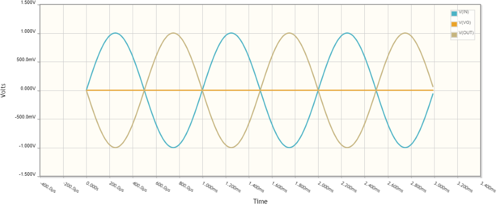
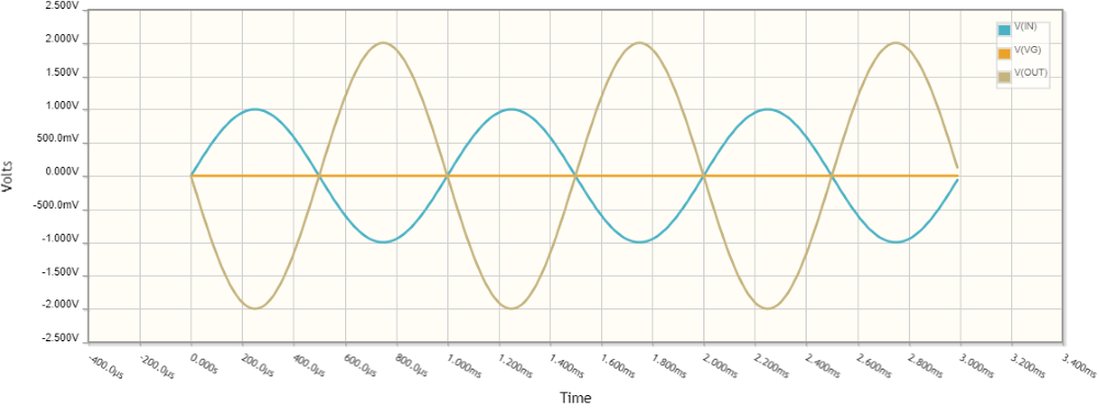
The op-amp now "observes" the voltage at its inverting input and adjusts its output voltage to keep it near zero (the H&H "golden rule"). As a result, Vout = -Vin.
STEP 11: Disturbed op-amp inverter
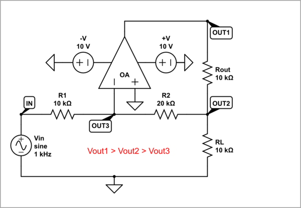
We already know how to convert a follower into an amplifier - by disturbing it with a proportional disturbance. The op-amp will sense this intervention through its inverting input and start raising its output voltage Vout in the opposite direction until it compensates for the disturbance. As a result, the equality will be restored, Vout = -Vin. But how do we disturb it?
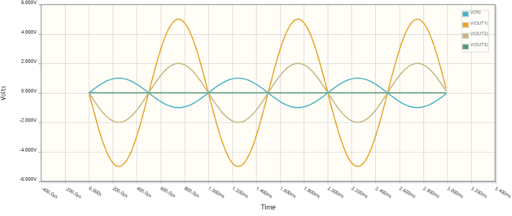
We can do it the same way we did it with the non-inverting amplifier - by including a "disturbing" resistor Rout in series with the op-amp output. In this way, we get an interesting amplifier circuit with three outputs. When using OUT1 as an output, it is the so-called inverting amplifier with T-bridge in the negative feedback (K >> -1); when using OUT2 - disturbed inverter (K > -1) and when OUT3 - inverter (K = -1). So the op-amp is disturbed twice - first by the voltage divider Rout-RL and then by the voltage divider R2-R1.
STEP 12: Op-amp inverting amplifier
But here this can be done very easily by increasing the resistance R2. Figuratively speaking, the input voltage source and the op-amp output "fight" each other to change the virtual ground point in their direction. So, increasing R2, we make it difficult for the op-amp to change the virtual ground and force it to increase its output voltage... thus becoming an amplifier.
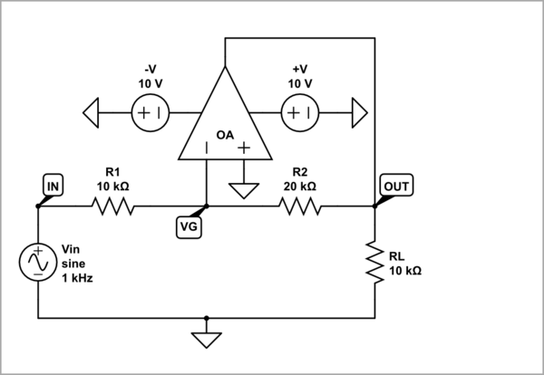
Now let's answer the possible OP's question for this configuration:
R1 = 0. The "disturbance" is infinitely high. In an effort to overcome it, the op-amp output voltage reaches the supply voltage (the op-amp is saturated).
R2 = 0. There is no disturbance (only R2 is in parallel to the load).
R1 is removed (open circuit). There is no input voltage. The circuit acts as a voltage follower with zero input and output voltage.
R2 is removed (open circuit). The "disturbance" is infinitely high. Striving to overcome it, the op-amp output voltage reaches the supply voltage with opposite polarity (saturated).
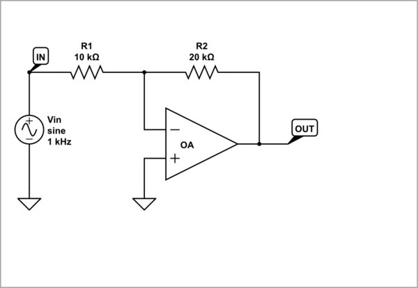
STEP 13: Conventional circuit diagram
Finally, let's draw the circuit diagram of the inverting amplifier in its conventional way to make the connection.
-
1\$\begingroup\$ Just a small remark (for a better understandung of the steps 5-8): For all shown equations - in particular X-Y=0 - we must assume that the open.loop gain A is approaching infinity. I think, this presumption was not yet mentioned, \$\endgroup\$– LvWCommented Feb 6, 2023 at 11:28
-
\$\begingroup\$ The problem was more technical - I couldn't find the symbol for "approximate":-) But I added a note in STEP 4 - "almost" in bold. \$\endgroup\$ Commented Feb 6, 2023 at 11:33
R1 and Rf are there to adjust the gain of the Op-Amp. You can observe that they make a voltage divider between Vout and GND. If R1 is replaced by a short circuit, the theoretical gain of the op-amp will become infinity. However, this is not possible in a practical scenario and the gain should become equal to the open loop gain of the op-amp. Hence, the circuit will effectively become a non-inverting amplifier without a feedback.
When you replace R1 by a short, theoretically, the gain will become infinity but that is not possible so your opamp gets saturated and the output is equal to +-(supply voltage).
What will happen if we replace it with a short circuit?
With R1 shorted to 0 volts, there will be no negative feedback and, no control of the circuit gain. All the benefits of a defined and controlled linear amplification are lost and the circuit becomes a simple comparator.

