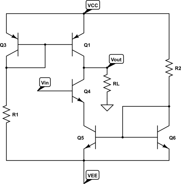
simulate this circuit – Schematic created using CircuitLab
I came with this circuit to know how an active load can improve it, I still can't finish to understand the role of active loads. The far I know is that below, Q5-Q6-R2 form a current source with gives the polarization DC current to Q4. Then I expect the circuit would be similar to a common emiter, but as I suggested on the title I'd be thankful if someone could explain me (suppose the components are perfectly matched):
-What's the purpose of using an active load Q1-Q3-R1 instead of a single resistor on the collector of Q4 and what advantage gives
-What could be a possible application for this circuit
Thanks if someone answer
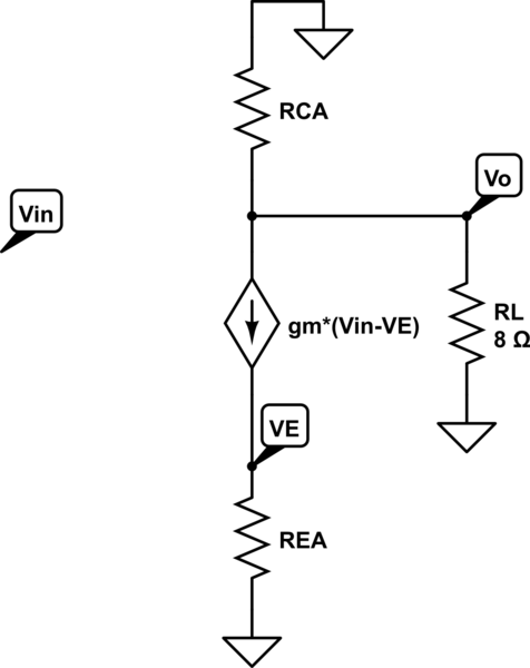
EDIT: Some research I did. Actually both upper and lower pairs are current sources and active loads. If they have the same reference current, they will polarize Q4 and the current on load will be 0. On the other hand, the AC circuit would be:

Since it must be that \$ V_E = g_m R_{EA} (V_{in} - V_E)\$, then:
$$ V_o = g_m (R_L//R_{CA}) v_{in} \left(1 - \frac{g_m R_{EA}}{1 + g_m R_{EA}} \right) $$
Where REA and RCA are the AC equivalent resistance of the AC model of the active loads. But they are function of frequency. And so, I looked carefully at the expression. Does this mean that the circuit could be a filter that dispenses with capacitors? I'm too drugged? What do you think?
