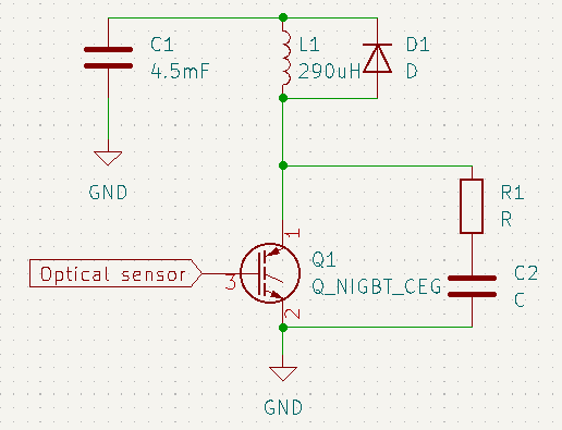
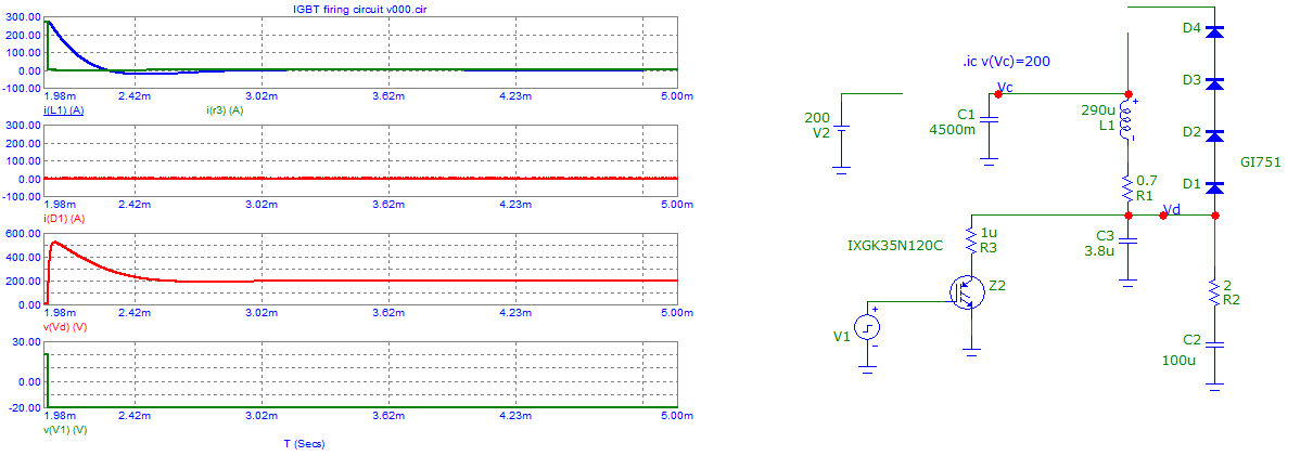
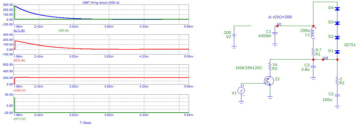
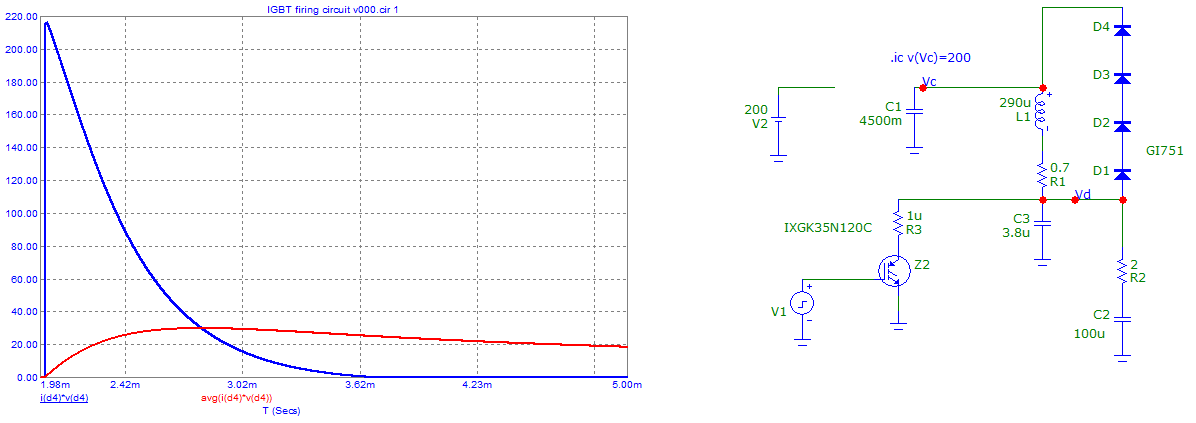
I'm working on an electromagnetic accelerator project but I'm having trouble protecting my IGBTs that switch current through the coils. Here's the schematic:
C1 gets charged to around 250 V (In my tests I only charged to 200 V) and is then placed in series with L1 when Q1 turns on. L1 has a resistance of 0.7 Ω so we expect 285 A when running at 200 V. So the energy in L1 is around 12 J. Q1 is an IXXH80N65B4 which is rated for 430 A surge an 650 V collector to emitter. So C2 has to hold 12 J of energy and not exceed 650 V which means C2 must be at least 56 μF and R1 must be at least 2.3 Ω.
I didn't have this size capacitor on hand, the next closest I had was 1 μF, but I wasn't too worried about this because I thought most of the energy would be dissipated by D1 and not much would be absorbed by the snubber. So I tested 1 μF with 4 Ω and this destroyed the IGBT and shorted all three pins.
I assumed 1 μF was too small, so I decided to try a much bigger capacitor to hopefully reduce the voltage spike since \$V=\sqrt{\frac{2E}{C}}\$. So I used a 1000 μF capacitor with the same 4 Ω resistor and yet again destroyed another IGBT. Not only that, but it also shorted the 1000 μF capacitor which was rated for 450 V. I don't know why this snubber isn't working. I thought it was safer to use bigger capacitors to limit the voltage?
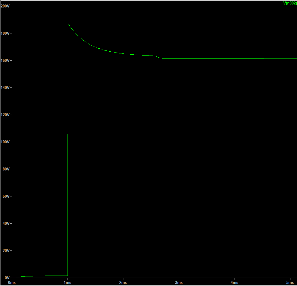
Simulation Results:
After simulating the circuit again the results are not the same as I remember (C2 is parasitic capacitance of IGBT between collector and emitter).
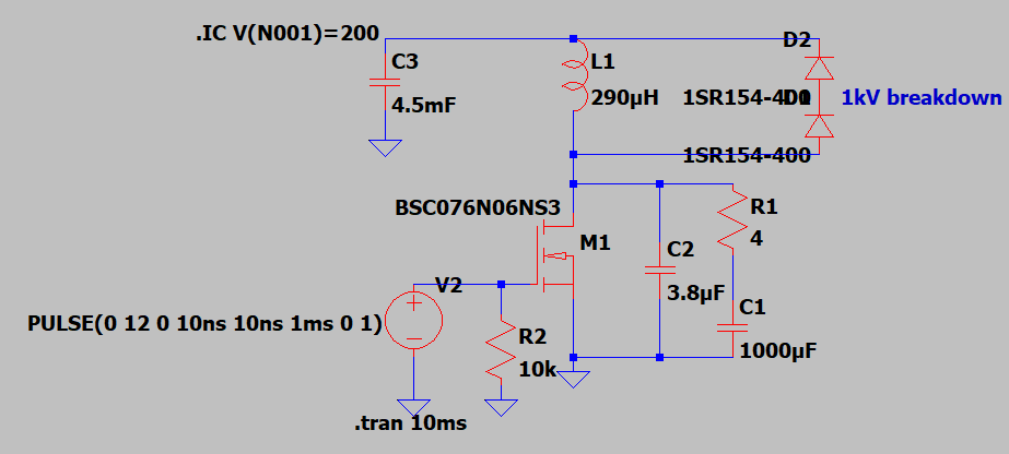
However, it seems LTSPICE thinks the snubber does not make a difference as when I remove R1 and C1 the plot remains the same. However, when I remove D1 we get this:
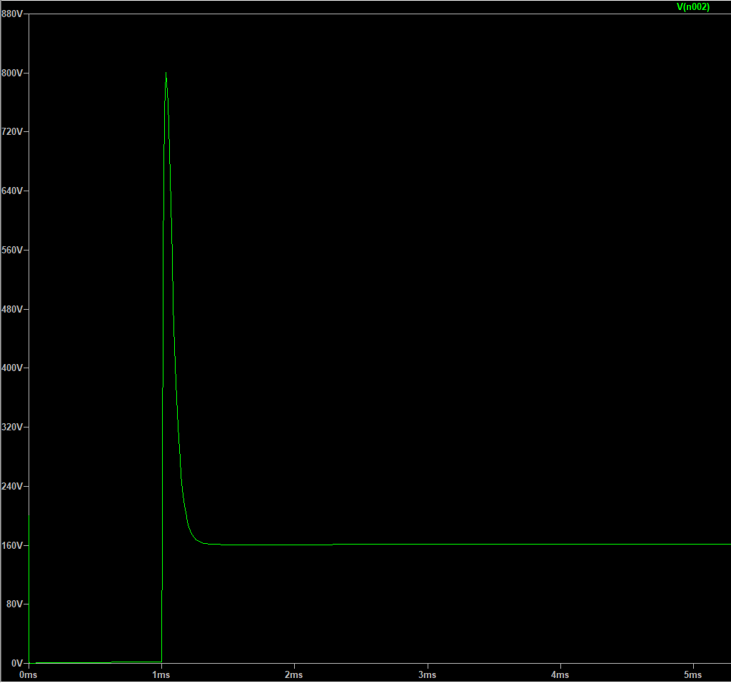 Which doesn't look too good! (The plot above is with 1000uF snubbing capacitor. If I use 1uF its even worse at 1.8kV peak). So could my diode be the issue and if so do high surge current schottky diodes exist? Or could I try to reduce this spike with just a snubber and no flyback diode
UPDATE:
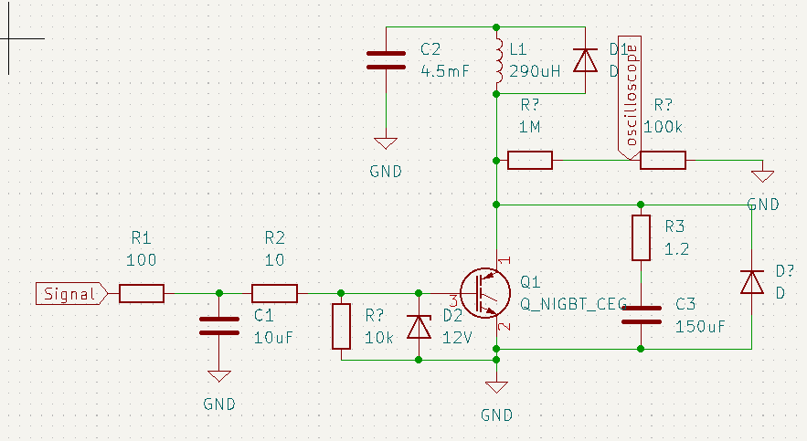
So I tried this again but this time with an improved circuit to hopefully protect my IGBTs. Here's the circuit:
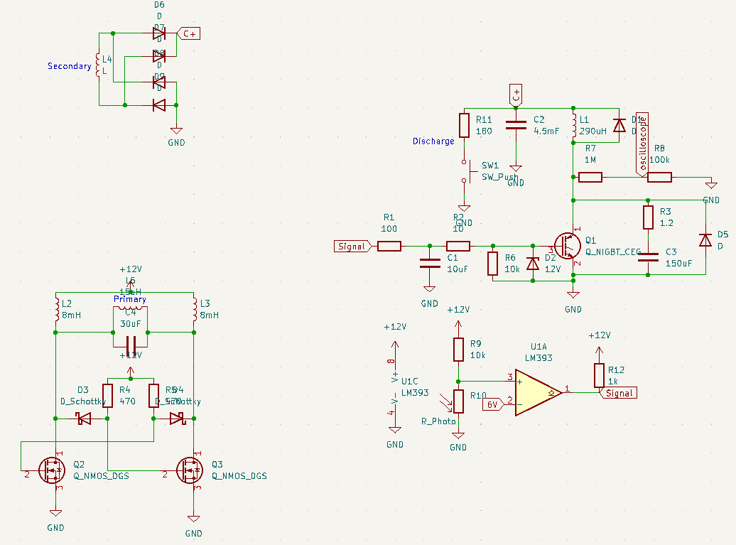
Changes include using a 1.2\$\Omega\$ resistor and 150uF capacitor for snubber as well as gate filtering and protection. I tested this circuit and it worked for 60V and 100V on C1. But then I tried 160V and the IGBT failed once again. However, I did not measure any overvoltage at the collector on the oscilloscope (The trigger level was set to the same voltage as the capacitor, taking into account the voltage divider, and it did not trigger meaning the voltage stayed below the capacitor voltage which is what simulations predicted). This has left me very confused as there is not over voltage on collector and I know the current through the IGBT is definetly within the IGBT's rating. I have more IGBTs to use but I don't want to destroy more. I have no idea what is wrong.
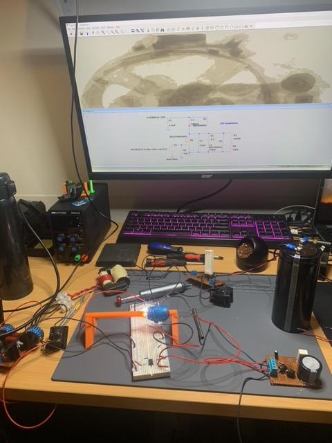
Here's a photo of the setup:
And here's a full schematic if it helps:
Another Idea:
I realised that my IGBTs are only specified for 430A for 1ms and 160A continuous in the datasheet. So depending on how fast the projectile moves it may need to sustain current larger than 160A for a few ms. I've seen others use IGBTs which are rated for 800A for 1ms instead and have had success running them at 400A for around 7ms. Is there any other safer option to get around this problem rather than getting even more expensive transistors and just hoping they can handle high current for more than 1ms?
UPDATE with new transistors:
So from my testing I thought excessive collector current was destroying my IGBTs so I got some 160N65B4 IGBT which can do 860A for 1ms. So I ran the circuit again and what do you know it breaks yet again. At this point I'm pretty lost on how to move forward, even if my flyback diode is too slow the snubber should control the collector voltage on it's own (assuming the transistor is on for 4ms or more which is reasonable on time from what I've researched). I checked over the circuit and moved components to reduce stray inductances. This included moving the flyback diode physically closer to the collector of the IGBT. However, the ground wire which connects the ground of the IGBT board to the battery ground is quite long and has around 2uH of inductance. I'm unsure how big of an issue this is but it does concern me given that any small inductance could be a big problem due to the high operating current. Should I be worried about this inductance? If not I'm all out of ideas.

