Background
I have designed a switch-mode power stage with voltage-mode control that uses an LCLC filter in its output to obtain a very low ripple output voltage.
I have empirically arrived at a compensation network that makes its control stable and provides a satisfying bandwith. I now want to carry out a proper small-signal stability analysis with this stable configuration as a starting point. The reason is that different values for the L and C can make it unstable again, so I want to simulate quickly how to adjust the compensation network.
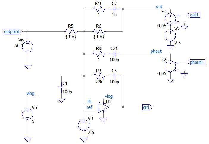
For this I have replaced the comparator with an op-amp and abstracted all the feedback paths as voltage sources (E1 and E2). The signal phout1 is the voltage after the first LC and out1 is the voltage after the second LC. The signal input is provided by V6 (also has a 2.5 VDC bias). This works very well to reproduce the transient behavior of the actual switch-mode circuit.
Question
I am interested in the gain and phase vs. frequency Bode plots, in a way that takes into account the lowpassing effect that appears when feeding the setpoint from V6 and R5.
Attempts
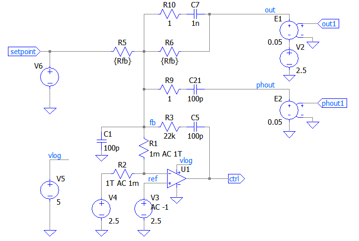
Below is shown what I tried. I found out that this method is equivalent to the so called "Middlebrook" method, i.e. it gives identical results. The examples by LTspice itself (e.g. Loopgain2.asc) also produce equivalent results.
I cut the AC feedback to the noninverting input and AC-ground it instead. Then I feed an AC 1 source into one of the op-amp inputs and monitor what arrives on the other end of the cut.
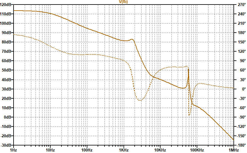
This is shown below. It produces a result that indicates that phase drops to 0 at about 2 kHz with 80 dB of gain left. The transient is fully stable in this case with Rfb=1Meg, but the input signal is also heavily low-passed, so maybe this is what makes it look stable. Does the low-pass simply prevent the destabilizing frequencies from ever occuring on the feedback node?
I tested the latter, by injecting my transient signal into V3 instead of V6. And indeed, it is now oscillating at frequencies that make sense in the context of the loop gain analysis.
That means, that the open-loop gain is correctly measured, but it doesn't take into account the stabilizing lowpass that signals experience when fed from V6 and R5.


.fradirective to be used with the newFRAsymbol to do these types of analyses directly. \$\endgroup\$