2
\$\begingroup\$

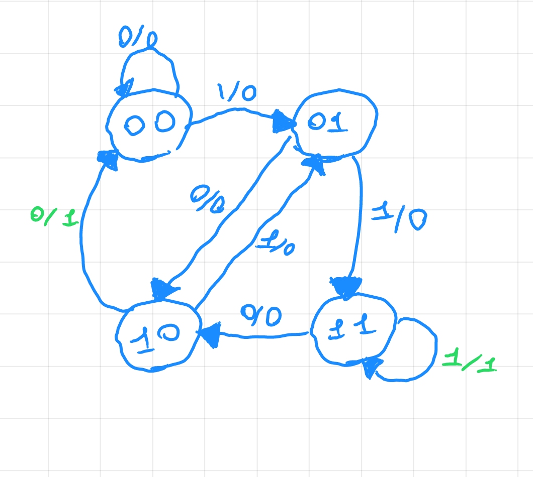
I need to design a pattern detector that recognizes 100 and 111 bit patterns, even overlapping ones. I drew the state diagram as shown in the image

enter image description here

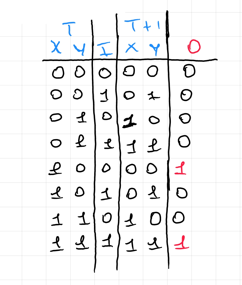
and created the related table

enter image description here

Could you tell me if it is correct? I also wanted to ask if the number of states is related to the number of bits (in this case the sequences are 3 bits, but could be for example 5) or if it comes from other data.

\$\endgroup\$
4
  • 1
    \$\begingroup\$ Looks good to me. Yes, the number of states is related to the length of the pattern(s) and the number of patterns, but it also depends on how much overlap there is among different patterns. \$\endgroup\$
    – Dave Tweed
    Commented Feb 8, 2023 at 22:30
  • \$\begingroup\$ I agree. This is what I get. Looks the same. \$\endgroup\$ Commented Feb 8, 2023 at 22:33
  • \$\begingroup\$ Ok thanks @periblepsis, now if I wanted to build a sequence detector that detects a 4 bit sequence (for example 1011) would 4 states be enough as in the example I developed here postimg.cc/7JVD5jTY ? Why in this case if we have 4 bits and not 3 as in the previous exercise does the number of states not change? I'm stuck on this concept. \$\endgroup\$ Commented Feb 9, 2023 at 7:36
  • \$\begingroup\$ @Dave Tweed No, overlap is not important. Design the logic for a single occurrence and you will find them all. For more detail, please check my answer. \$\endgroup\$
    – Borg Drone
    Commented Feb 12, 2023 at 12:07

1 Answer 1

2
\$\begingroup\$

In this particular case, I recommend you to use a serial-in parallel-out register. With it you would only need to connect the serial input to the data stream, connect the shift clock to the same clock your data uses to change state and then using the first n bits of the parallel output to apply your logic.

As data is being inputted serially, every cell in the shift register is being replaced by the next one. As the logic would only check three consecutive bits it would always find all occurrences, without caring about them being overlapped.

There are other ways, like designing an automat as you are already doing; but that may not be necessary as the logic you describe does not seem to alter the states of the fsm and just generates the output (therefore doing exactly the same).

In your case with your 3-bit sequence equation would be:

Result = Bit_2 AND (Bit_1 XNOR Bit_0)

Why this equation? Assuming you need an active high output (result is true if conditions met) you will always require the higher bit to be 1. About the other two, you don't care about the exact value of them but both must be equal. Gate XOR always returns true if different, therefore using its complementary (XNOR) we will obtain a true if its inputs are equal.

To complement this wall of text, I append this schematic for refference:
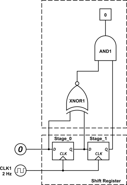
schematic

simulate this circuit – Schematic created using CircuitLab

Answering to your last comment in your question: if you wanted to expand the circuit and check for more bits, more stages of the shift register shall be used and logic modified. The number of stages you would be using is the number of bits of your pattern minus one, which is taken directly from the input.

I hope it helps

\$\endgroup\$
10
  • \$\begingroup\$ It depends on what you're trying to optimize. The shift register technique is certainly straightforward to design, and for short patterns may use the same number of FFs as the type of state machine the OP is asking about. But for longer patterns, it requires more FFs than the state machine. \$\endgroup\$
    – Dave Tweed
    Commented Feb 12, 2023 at 13:07
  • \$\begingroup\$ @DaveTweed I disagree. Remember that the system should detect overlapping patterns. If you implemented the finite state machine in a way that stored a bit to represent if the sequence is correct to that point without storing the sequence per se, you would need another flip flop for the next recognized pattern, and if the pattern to be found is large enough you would need a flip flop for each of the overlapped occurrences. For this reason I think it is important to store it and treat it as it comes. \$\endgroup\$
    – Borg Drone
    Commented Feb 12, 2023 at 13:15
  • 1
    \$\begingroup\$ No, you don't need a FF for each occurrence, you need a state. The number of states grows roughly linearly with the number and the length of the patterns, but the number of FFs only grows logarithmically. With your technique, the number of FFs grows linearly with the length of the pattern(s) -- and the number of states grows exponentially -- regardless of anything else. \$\endgroup\$
    – Dave Tweed
    Commented Feb 12, 2023 at 13:23
  • \$\begingroup\$ (1) Your point is good but I don't share it. As you said, the number of states duplicates with each bit added. You could do it with a one bit state to represent correctness of the input sequence, and a n bit value to represent the current step; outputs being correctness (only set once the pattern has been completely processed), the expected value of the input to compare with the actual value and next state. That would keep the number of state bits pretty low for long sequences. \$\endgroup\$
    – Borg Drone
    Commented Feb 12, 2023 at 14:01
  • 1
    \$\begingroup\$ See the writeup that I did some time ago here. Also here. \$\endgroup\$
    – Dave Tweed
    Commented Feb 12, 2023 at 15:08

Your Answer

By clicking “Post Your Answer”, you agree to our terms of service and acknowledge you have read our privacy policy.

Not the answer you're looking for? Browse other questions tagged or ask your own question.