1
\$\begingroup\$

In order to start or reboot the PC, the PIKVM must have (shared) control to the frontpanel pins of the PC. In this GitHub article they say relays, wires and resistors are required:

For ATX control (optional):

  • 4x MOSFET relays OMRON G3VM-61A1.
  • 4x 390 Ω resistors.
  • 2x 4.7k Ω resistors.
  • A breadboard and wires.

But why is a relay and why are resistors with different values required? How is the right resistance determined, would resistors with lower/higher resistance also work? Wouldn't it be enough to e.g. short the restart wires, so that a simple splitter cable would already do the trick?

Unfortunately, I can't find any schematics. The documentation of PIKVM is either not very good, or I simply can't find it.

\$\endgroup\$
3
  • \$\begingroup\$ Sure a splitter will just split the wires and it will do to extend to a second button if you wish, but how do you expect the Pi to simulate a push button unless you use a relay? Also, unless you can provide a schematic, we can't possibly know how they are intended to be connected and where, or even assess if their values are correct or if different resistances will work. We don't know if the design is of random hobby circuit quality which should not be built or if it is a professional design with far better parts than what is required for the task. \$\endgroup\$
    – Justme
    Commented Feb 14, 2023 at 22:32
  • \$\begingroup\$ That is another problem: There is simply no schematic. Unfortunately the documentation for PIKVM is not very good. I assumed that the relays functionality is provided directly over the GPIO of the Raspberry itself but it seems not. \$\endgroup\$ Commented Feb 14, 2023 at 22:38
  • \$\begingroup\$ A relay is a universal replacement for a pushbutton, it works all the time, whereas other ways to replace buttons are dependent on how the button is wired into the circuit. \$\endgroup\$
    – user20574
    Commented Feb 14, 2023 at 23:26

2 Answers 2

2
\$\begingroup\$

The "relay" is an optically isolated MOSFET switch. The isolation, or relay action is useful because it lets you control circuits with different power supplies without worrying about bad things happening.

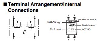
It has an IR LED internally, and that drives a set of MOSFETS. The 390Ω resistors are placed in series with the LED to limit the current. For a 5V system (ATX side), 390Ω limits the current to about 10mA. You can see the internal connections in the datasheet figure below:

enter image description here

The current required to reliably "trip" the relay is just under 3mA. As long as you adjust the LED resistor to allow more than that, it will reliably switch. Increasing the current makes it switch faster, but that probably isn't important. Any current value greater than 3mA and less than 25mA is good, though you may need to keep it on the lower end for the drive circuits.

enter image description here

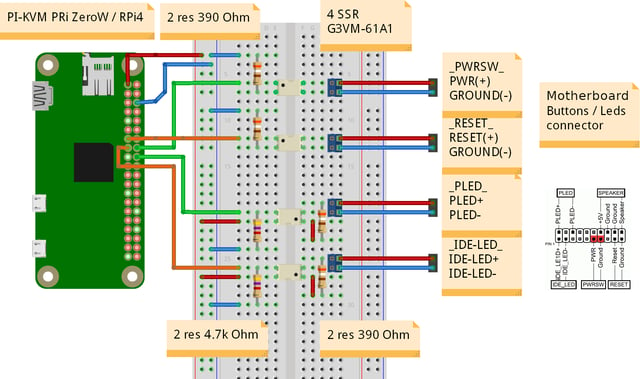
Under the section "Setting up the V2" I found the following diagram. The 4.7kΩ resistors are used to provide a pull-down to provide a digital logic value for the PI side of the system when the LED is "off". enter image description here

\$\endgroup\$
9
  • \$\begingroup\$ Thanks so much! Now that makes sense with the resistors and so I know that I can also use my 330 Ω resistors since that would be a safe value (= 15 mA). You wrote for 390 Ω it would be about 10 mA at 5 V, but isn't it to almost 13 mA? \$\endgroup\$ Commented Feb 14, 2023 at 23:33
  • \$\begingroup\$ So my assumptions were correct. And it is a very odd circuit then. It makes little sense to add extra resistors for the optorelay, if the motherboard already is intended to drive LEDs directly and thus already has built-in resistors, so there may be lower current than recommended for the optorelay input. It will work without resistors if the polarity is correct. Which is also an odd choise to require polarity, because the relay output side can be connected in any polarity to the button pins. Some motherboards do not state which pin is ground and which is signal, so it will work in any polarity \$\endgroup\$
    – Justme
    Commented Feb 14, 2023 at 23:34
  • \$\begingroup\$ Good point. Maybe PLED and IDE-LED are even driven by limiting the current instead of using a resistor, but I am not sure. Do you think that also applies to PWRSW and RESET? \$\endgroup\$ Commented Feb 14, 2023 at 23:51
  • \$\begingroup\$ @Tintenfisch Current limiting is just simplest with a resistor. But any motherboard manufacturer can implement whatever they want on the front panel interface. They should be just raw buttons and raw LEDs so any circuitry possible could be implemented to interface them, and therefore, no assumptions should be made how they are implemented. For example, the LED could be switched from the anode or cathode side, and the resistor could be on anode or cathode side. And the supply voltage could be modern 3.3V or legacy 5V. And same for buttons. There is no standard that says how it should be. \$\endgroup\$
    – Justme
    Commented Feb 15, 2023 at 8:39
  • 1
    \$\begingroup\$ I'm not certain whether the standard case LED has its current-limiting resistor on the motherboard or in the case (on a small circuit board). It's definitely safer to include them as a "common" value of resistor would probably only halve the current to the relay IC. The circuit seems very reasonable to me, I wouldn't recommend deviating from it. Minor changes in resistor values will probably not cause any issues (e.g. next value up or down). \$\endgroup\$
    – W5VO
    Commented Feb 15, 2023 at 18:22
2
\$\begingroup\$

GPIO pins do not look like relays to arbitrary signals found on random pushbuttons. In fact that is a sure way to damage things if assumed that they can be just randomly connected together.

What you need to know how a typical reset or power button in a PC works. One wire might be ground, and the other wire may be the signal that needs to be grounded to activate an action. The pushbutton shorts the wires together to trigger the action.

Now, even with that assumption, you don't know which wire is which. You also don't know what is the idle voltage on the signal wire when it is not grounded. It might be 5V which might fry your GPIO pin which can't tolerate 5V. You also don't know how much current will flow when the signal is grounded. It might be few milliamps, or like I once encountered, tens of milliamps, which can't again fry your GPIO pin if you tried to drive it.

So that's why a relay is used as an interface between two circuits.

GPIO pins can be used to control a component such as a relay (electromechanical or solid state like in this case) which can then be used to replace a pushbutton.

Unfortunately you only have a list of parts, but no information how the parts are connected. Like parts for a house but without blueprints you don't know how to build it or how the parts are used. There is no information why 4 relays is needed and what functions they control and in which direction.

Safe to say that GPIO is used to control the solid state relay, which can then be used in place of physical push button.

The solid state relay can basically replace a LED so current limiting resistor is needed.

Assuming the 390 ohm resistors are used for current limiting, it can likely work fine with 3.3V and 5V.

No idea for what the 4k7 resistors are for, but they may be pull-ups.

\$\endgroup\$

Your Answer

By clicking “Post Your Answer”, you agree to our terms of service and acknowledge you have read our privacy policy.

Not the answer you're looking for? Browse other questions tagged or ask your own question.