2
\$\begingroup\$

I am trying to make a homebrew power supply. It works at the moment, but compensation is not done yet.

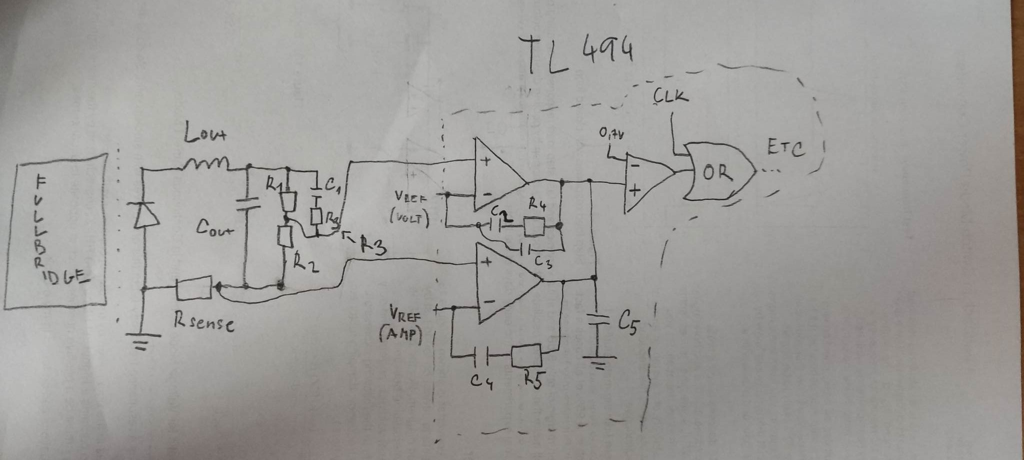
Can someone help me to calculate and select the right poles and zeros? VCM is at error op-amp 1, curent mode at error op-amp 2.

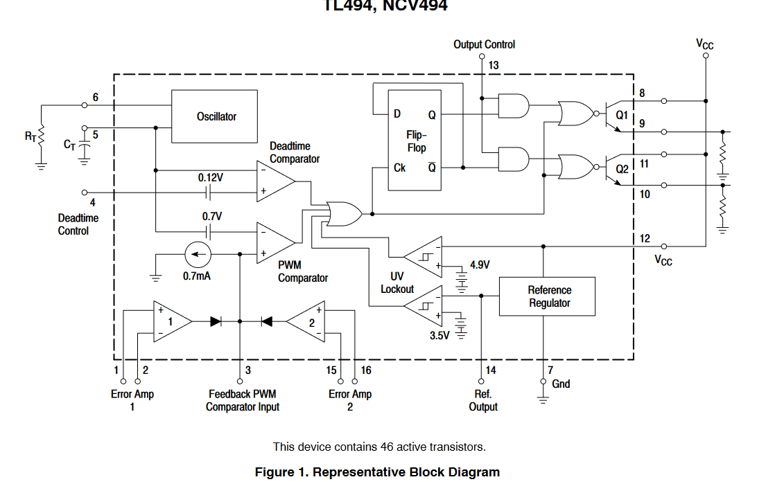
Reference voltage is set at negative input by potentiometer (Vset), feedback voltage is fed to positive input (Vsense). When the output of the error op-amp is higher than 0.7 V -> TLT494 hald clock signal, so feedback needs to be connected to +Vin to maintain negative feedback.

I have tried to set it without calculations, but I am not able to find the correct combination that will work at variable loads.

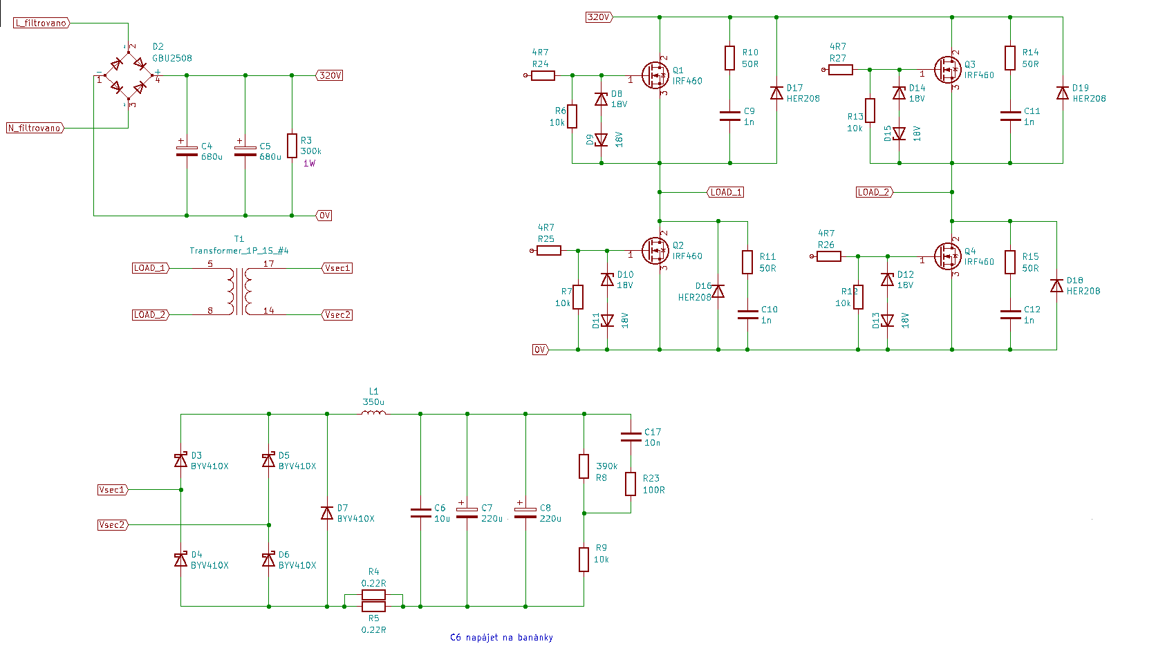
The PSU is 0-200 V, 5 A. The transformer is noisy; when values are not set properly, the transformer fizzes, or makes a high-frequency noise. When it's set correctly it works and is quiet, but when the load changes it starts fizzing.

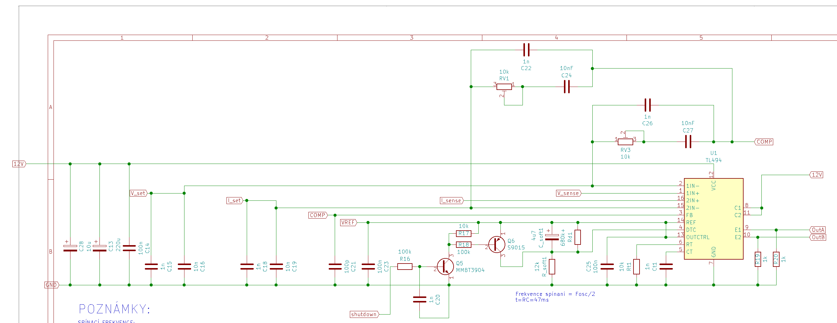
enter image description here

enter image description here

enter image description here

enter image description here

enter image description here

\$\endgroup\$
10
  • 1
    \$\begingroup\$ I don't see any power stage with transistors and transformer here. Can you please simplify the schematic and show an equivalent circuit where we see the control, the power stage and the return path. Děkuji : ) \$\endgroup\$ Commented Feb 23, 2023 at 21:05
  • 2
    \$\begingroup\$ Ok, what you need is the control-to-output transfer function of this full-bridge converter. You can extract it from your prototype but I doubt you are equipped with a frequency-response analyzer (FRA). The best is to run a simulation using one my free templates. You will have to make a simplified model of the internal modulator in the TL494 then run an ac analysis. Once you have the transfer function, you can think of a compensation strategy. \$\endgroup\$ Commented Feb 24, 2023 at 9:10
  • 1
    \$\begingroup\$ @Verbalkint I own hacked MSO5072 which can do bode plots, but i dont have an injection transformer. So i guess i need to make one. I think i am to much "stupid" atd the moment to create my own simplified model of tl494... I have noticed that you wrote some books. Are any of them "newbie friendly" ? =D I am learning it at my own... \$\endgroup\$ Commented Feb 24, 2023 at 10:27
  • 1
    \$\begingroup\$ I will see if I can simulate a quick circuit and document it in the answer. I would need the transformer turns ratio (with its mag inductance value though it's relevant in VM) and the output cap. ESR as well for the output inductor. Thanks. \$\endgroup\$ Commented Feb 24, 2023 at 15:30
  • 1
    \$\begingroup\$ Transformer is 52 turn primary, 39 secondary, primary inductance was i think 11mH. turns ratio p/s is 1,335. Output capacitence of one capacitor (two parralel) is 190uF and ESR is 0,18R and resistance of output inductor is aprox 50mOhms. Thanks for help \$\endgroup\$ Commented Feb 24, 2023 at 18:09

1 Answer 1

5
\$\begingroup\$

As I said in the comment, I realized after documenting the entire reply that the TL494 was using an unconventional op-amp configuration where the feedback voltage must increase to reduce the duty ratio. Therefore, you need to configure the op-amp in a non-inverting mode which is 100% non-standard. Besides, the data-sheet documents a design example in which the converter is operated in an uncompensated closed-loop configuration so I can imagine the transient step response...

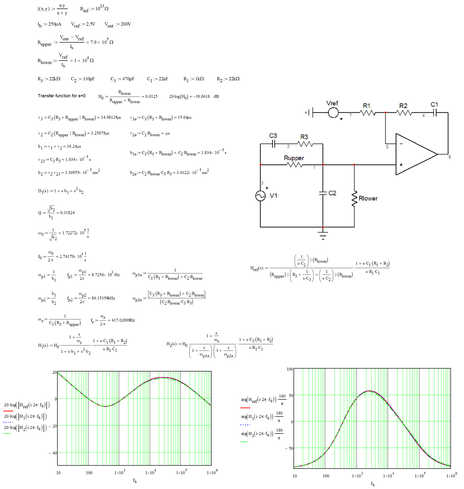
Anyway, I looked at how to derive the transfer function of a non-inverting type 3 configuration and the equations are below:

enter image description here

I did not exactly derive the design equations to perfectly extract each components values but what I got in simulation looks ok to me. You will let me know if your experiments confirm my approach. Please note that resistance \$R_1\$ is the output resistance of the voltage divider bringing 5 V down to 2.5 V.

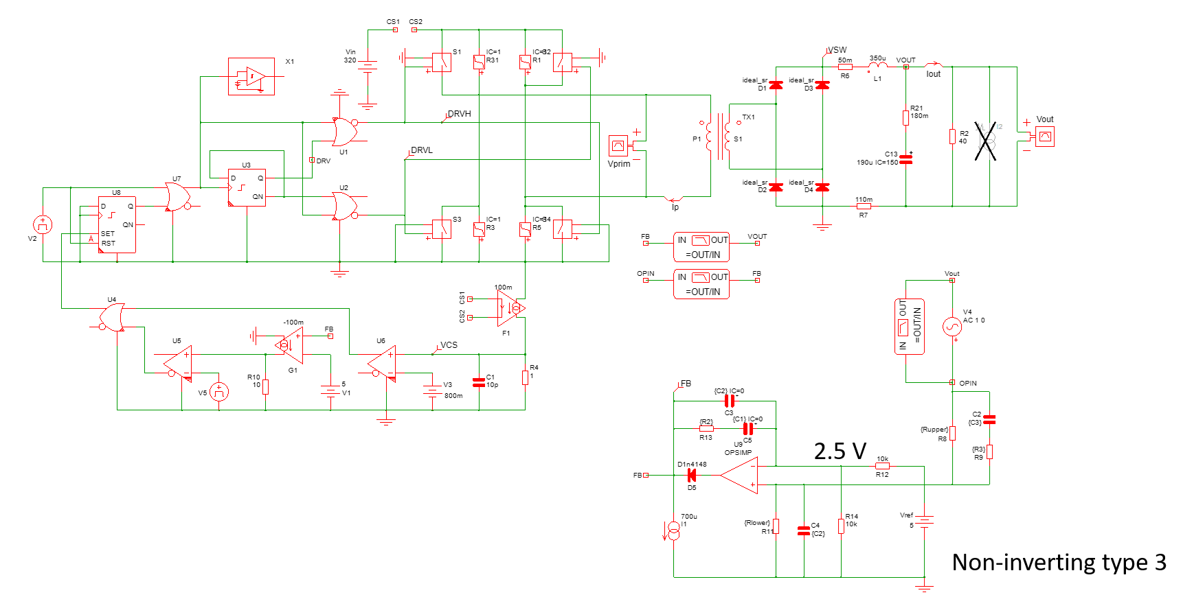
The simulation circuit is here:

enter image description here

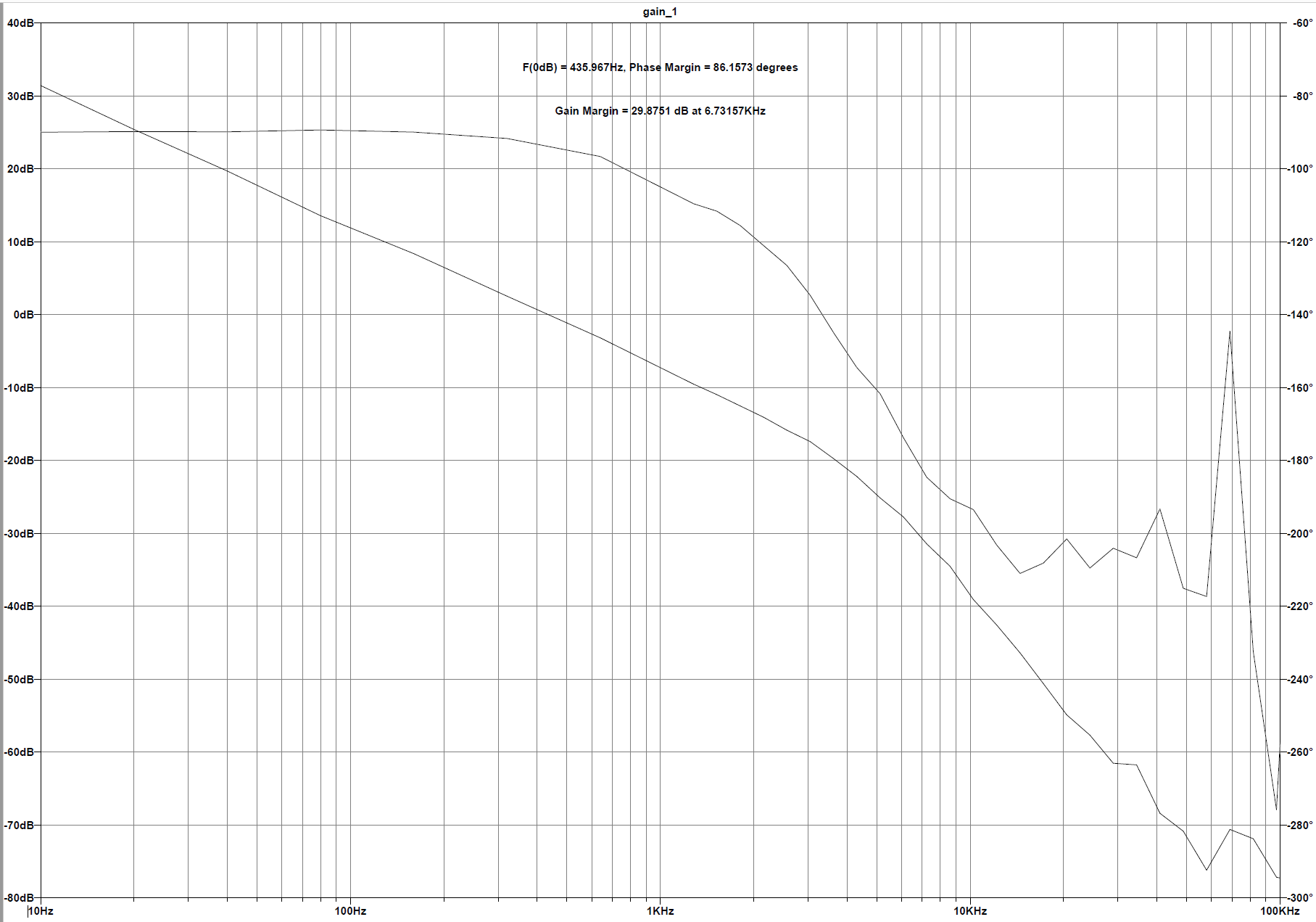
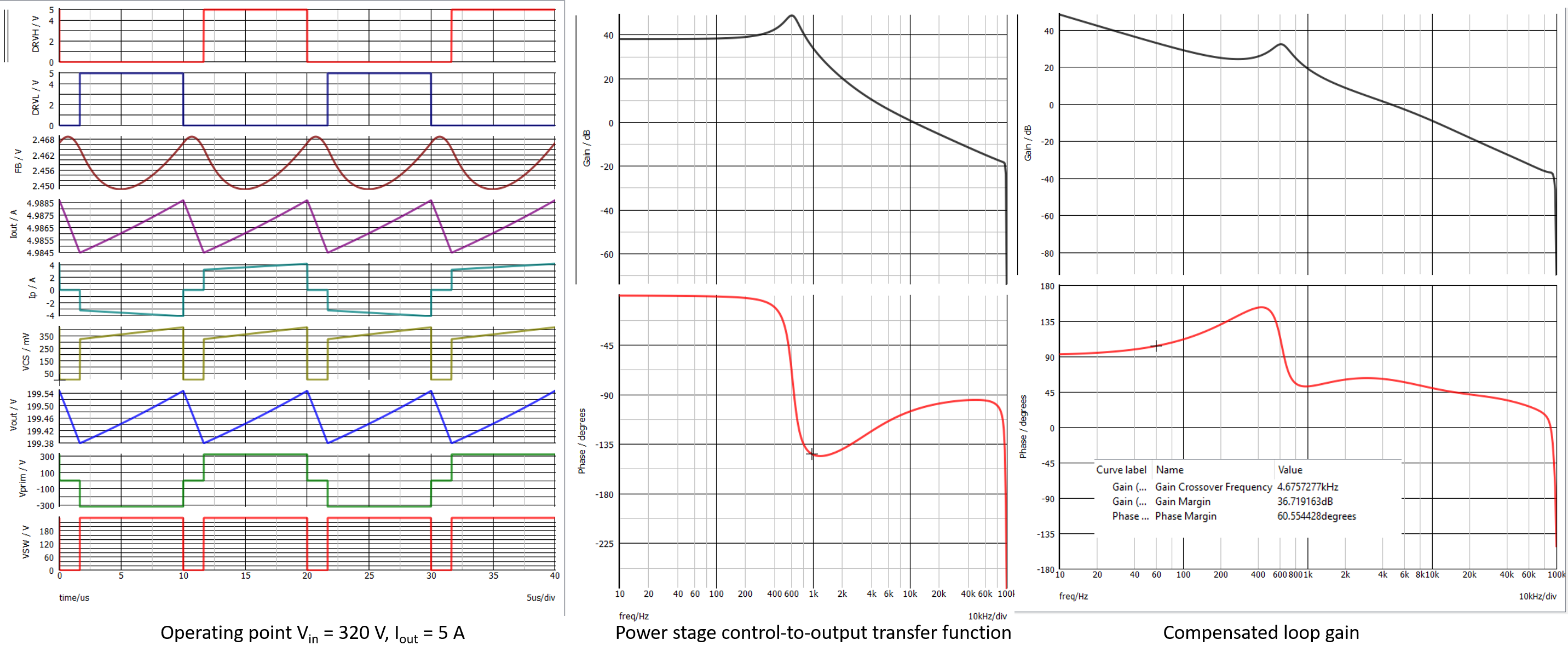
The ac response of the circuit is immediately delivered by SIMPLIS:

enter image description here

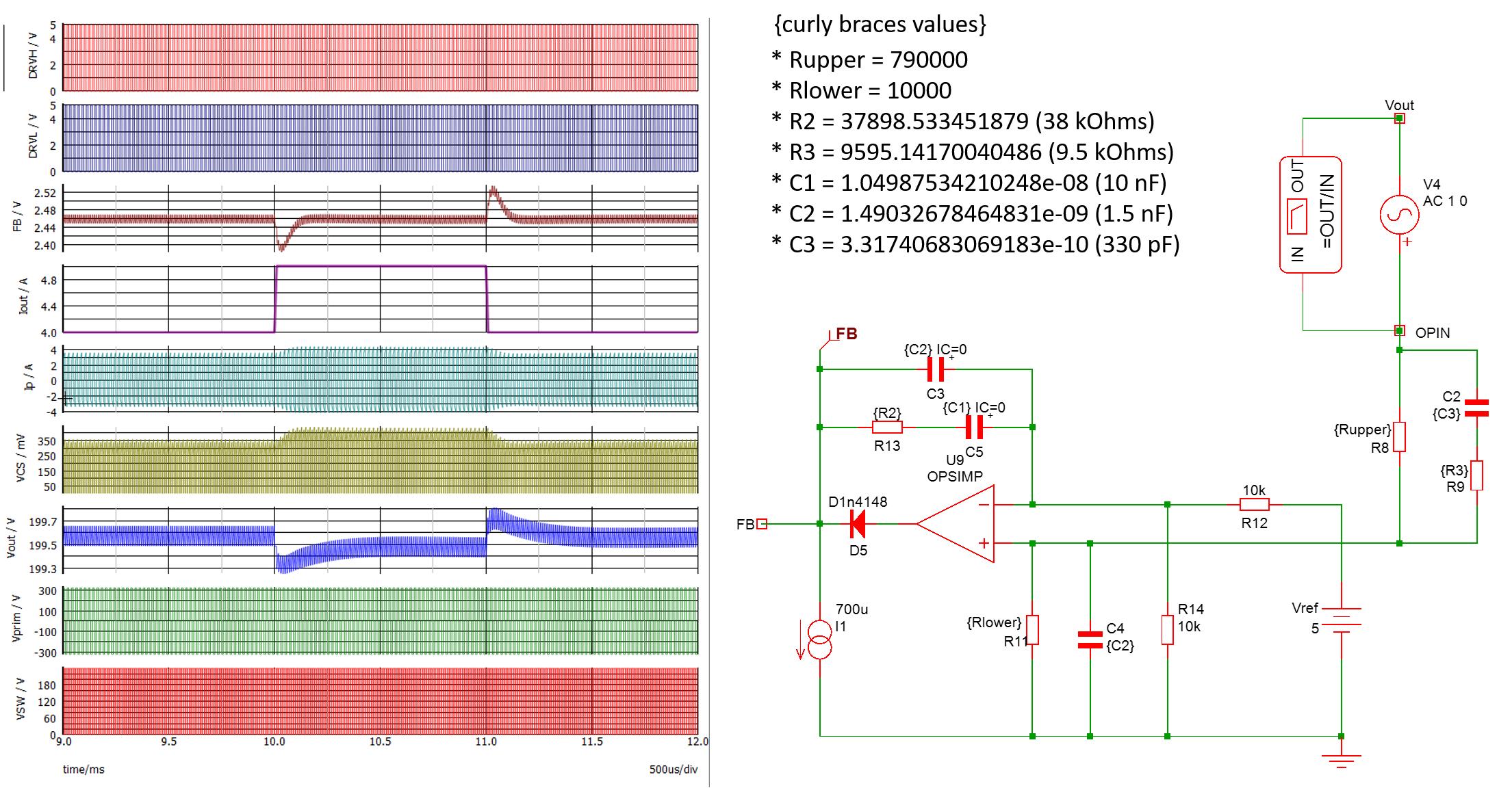
and finally, the transient response looks good too:

enter image description here

I added the computed values, please let me know how it works. If it does stabilize the power supply, I'll look into the current loop then. Good luck!

\$\endgroup\$
8
  • \$\begingroup\$ So first impressions=). I have changed parts to corespond to yours computed values and wow =), it works way better then before. There is only little gap in full range when transformer starts fizzing but yeah its way more quiet. I should note that i have noticed that you have only one cap at output, there sould be 2x 190uF, sorry for missunderstood. Also i dont have 1.5nF and 330pF so i have used 1nF and 470pF instead. I should do some tweaking with resistors then. Maybe it will be beneficial if this topic rename to "TL494 compensation". May i ask where did you find how to compute it? Book? \$\endgroup\$ Commented Feb 26, 2023 at 9:53
  • \$\begingroup\$ and thanks very much =) \$\endgroup\$ Commented Feb 26, 2023 at 10:04
  • \$\begingroup\$ I checked and adding a second 190-µF capacitor reduces slightly crossover but does not affect stability. Detailing the compensation procedure is difficult in a comment window but, basically, you start with the control-to-output transfer function (TF) and identify where to set crossover (\$f_c\$). 3-5 times the resonance in voltage-mode control and then you tailor the active filters to fight the phase lag and provide gain or attenuation at the selected \$f_c\$. The list of seminars \$\endgroup\$ Commented Feb 26, 2023 at 12:27
  • \$\begingroup\$ ...I provide contains many information on how to stabilize a converter. Have a look at APEC2019 which shows how to compensate a buck converter. Not much different here except that this is a non-inverting structure. Glad it works better now. The transformer making noise can be also linked to noise pickup and may not necessarily be a stability issue. If you liked the details I gave, please acknowledge my answer as the correct one, děkuji! \$\endgroup\$ Commented Feb 26, 2023 at 12:33
  • \$\begingroup\$ I would like to try some of those simulators. I have looked at Simetrix Elements but it seems its limited in number of components. I have found microcap 12 which is free. Would you recomend me something for learning purposes? I am not student nor employe. Its just for self learning purpose \$\endgroup\$ Commented Feb 27, 2023 at 9:29

Your Answer

By clicking “Post Your Answer”, you agree to our terms of service and acknowledge you have read our privacy policy.

Not the answer you're looking for? Browse other questions tagged or ask your own question.