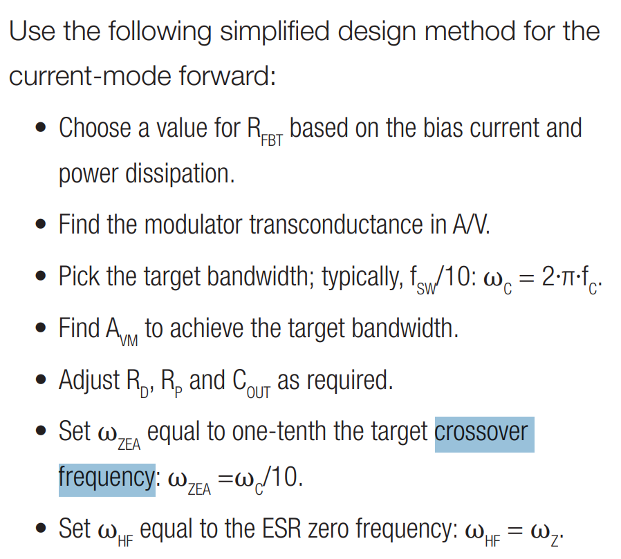
Taken from the Switch-mode power converter compensation made easy , what is crossover frequency, and how do I determine what it should be?
-
1\$\begingroup\$ Crossover frequency is the frequency when the gain is equal to zero. You could check the figure 4 (a Bode plot) in the document you have just shared. Simply put, the rule of how to choose it is one-fifth to one-tenth the switching frequency, which is also mentioned in your document (page 4). If you want to learn more about it, Christophe Basso's books are strongly recommended. cbasso.pagesperso-orange.fr/Spice.htm \$\endgroup\$– T LCommented Mar 5, 2023 at 3:47
-
\$\begingroup\$ @TL please post that as an answer \$\endgroup\$– Voltage Spike ♦Commented Mar 5, 2023 at 5:36
-
\$\begingroup\$ @TL that doesn't ring true. For a low pass filter, the frequency where the gain equals zero is infinity. If you google the term (a term I never use) it just lists things to do with loudspeakers. \$\endgroup\$– Andy akaCommented Mar 5, 2023 at 11:30
-
\$\begingroup\$ Thanks for reminding! What I have learned may not be comprehensive enough, which is why I only post a comment but not an answer. I am waiting for a more comprehensive and authoritative explanation! Like the answer given by Mr.Christophe. \$\endgroup\$– T LCommented Mar 5, 2023 at 13:00
1 Answer
You can have a look at the answer I gave on SE some weeks ago. Basically, the selection of the crossover frequency, as pointed out by TL in his comment, sets the frequency at which the loop gain magnitude is unity or 0 dB in a logarithmic scale. That loop gain, noted \$T\$, is the product of the power stage control-to-output transfer function, noted \$H\$, by that of an active filter - the compensator - (noted \$G\$) that you must design: \$T(s)=H(s)G(s)\$.
Before crossover, when the loop gain is greater than 1 then the control system, in ac, is operational. Simply put, no gain, no feedback. That means that if you have a disturbance whose frequency is in the region where the loop gain magnitude is high, this disturbance will be vigorously fought by the control system. For instance, the 100-Hz rectified ripple across the bulk capacitor is a disturbance that is well rejected if the loop gain magnitude is high at 100 Hz. If it is poor instead, then the 100-Hz ripple won't be efficiently rejected and will show up on the output. If you have set the crossover at 1 kHz for instance and you now have a disturbance at 10 kHz, then there is no loop gain at that frequency and the control system operates in ac open-loop: it does what it can to fight the perturbation but the compensated loop is inert in ac because it has no gain. Of course the dc point is kept but the ac modulation goes through and can't be rejected.
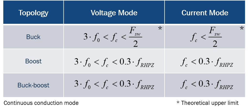
I am always cautious with statement indicating that crossover \$f_c\$ must be picked at a tenth or so of the switching frequency. As shown in the below table, it depends on the converter:
The lower the crossover, the slower the system and, on the opposite, the higher the crossover and the more reactive/nervous the system becomes. Too high a crossover value makes the converter more susceptible to noise (operating like the switching ripple but also external). So crossover, within the limits given in the table, must be set to meet transient goals (robustness to perturbation, response time etc.) and not more. More information is available in my APEC 2021 seminar.


