0
\$\begingroup\$

I have an ATTEN ADS1062CML 60 MHz 2-channel digital oscilloscope and it has quite poor input sensitivity. My idea is to build a 2-channel low-noise pre-amplifier. I mostly need the oscilloscope for debugging vacuum tube audio circuits.

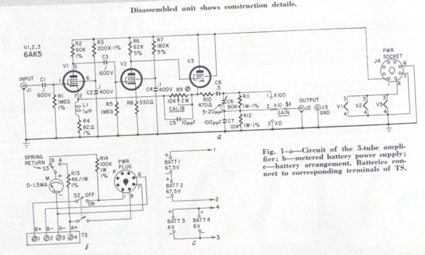
I came across an article "Measure Milli-volts with Decade Amp" in Radio Electronics magazine 1960-09, which describes an add-on for a voltmeter or oscilloscope. It has a gain of 100, 5 Hz - 1MHz bandwidth, 1 MΩ input resistance, 1 kΩ output impedance, and because of the vacuum tubes used (3 x 6AK5), it is immune against input overload. Noise with input shorted is 300 μV. Overload input voltage is 0.25 V.

My idea is to build two channels, power it with separate HV windings of a toroidal transformer, and make separate GNDs for each channel.

Also, I would like to replace the 1 MΩ grid leak resistor with a series of 3 to make 1/10/100 attenuation of the input signal, so there will be no need for countless switching of the oscilloscope probes between this pre-amplifier and the digital oscilloscope.

What is your opinion? Is this a good idea?

Schematic

\$\endgroup\$
7
  • 1
    \$\begingroup\$ why would you use something so finicky for measurement purposes? The 1960s invented the integratable operational amplifier exactly for the reason of not having to deal with tube amplifiers and their imperfections as linear amplifiers. \$\endgroup\$ Commented Mar 10, 2023 at 20:49
  • 1
    \$\begingroup\$ I mean, why would you connect a digital-era measurement to a tube-era amplifier? that just feels like putting the horse in front of the cart – just that the cart is a modern car. \$\endgroup\$ Commented Mar 10, 2023 at 20:50
  • \$\begingroup\$ Perhaps the question should be edited - it is literally asking for opinions if building this is a good idea. Depending on who you ask, it might be a good or bad idea, and that should have nothing to do with if you build it or not. However, as already presented, more modern options do exist, but if they are better will also be subjective. Some people like tubes, some people like op-amps. The problem might also be how you use the scope. Do you use 1x or 10x probes? \$\endgroup\$
    – Justme
    Commented Mar 10, 2023 at 21:40
  • \$\begingroup\$ @Justme on one hand, I agree – this asks for opinions. Then again, it says "low noise preamplifier" as requirement. So, there are objectively evaluatable criteria: 1. noise figure, 2. suitability as measurement preamp. \$\endgroup\$ Commented Mar 10, 2023 at 21:42
  • 1
    \$\begingroup\$ You are all missing the fact that it is to be used to make measurements on vacuum tube equipment. It seems to me like a vacuum tube front end would be a good idea. It'll certainly be better able to stand up to accidental exposure to the high voltage (250V B+) in the tube amplifier being tested. \$\endgroup\$
    – JRE
    Commented Mar 10, 2023 at 22:23

1 Answer 1

1
\$\begingroup\$

Opamps.

A gain of 100 at 1 MHz is a very large gain-bandwidth product. I would go with a low-noise, FET-input opamp, something relatively wide band, and have two of them in series, each configured for a gain of 10. Two zener diodes are all the protection the input would need.

Jim Williams was a fan of compound amplifier circuits. In this case that would be a two-opamp circuit for the gain-of-10 stage, with ome opamp optimized for its input characteristics, and the other optimized for bandwidth and output impedance/current.

That would be four opamps total per channel. Now you can meet just about any combination of input impedance, input noise, input stage harmonic distortion, output stage bandwidth, etc.

\$\endgroup\$
3
  • \$\begingroup\$ It might be possible to do in a single stage with a current-feedback amplifier, too. \$\endgroup\$
    – Hearth
    Commented Mar 10, 2023 at 21:48
  • \$\begingroup\$ What steps will you have to take to make the op-amp circuit sturdy enough to stand up to accidental exposure to the B+ voltage of the vacuum tube circuits the OP is planning to test? What effect will those steps have on the accuracy and frequency response of the op-amp circuit? \$\endgroup\$
    – JRE
    Commented Mar 10, 2023 at 22:26
  • 1
    \$\begingroup\$ Current feedback would not be my first (or second) choice for low noise / low distortion audio work. \$\endgroup\$
    – AnalogKid
    Commented Mar 11, 2023 at 4:17

Your Answer

By clicking “Post Your Answer”, you agree to our terms of service and acknowledge you have read our privacy policy.

Not the answer you're looking for? Browse other questions tagged or ask your own question.