15
\$\begingroup\$

I want to make a wooden chess board that you can play on with regular pieces (i.e., not modified pieces that make use of RFID codes, magnets, …), but that is connected to a software that takes notice of my moves and acts as the second player.

I have been thinking about how to detect pieces on the board, and I have made the decisions that I do not need to recognize which piece is where: The "truth" is within the software, so if I move a piece from A to B, the software is able to find out which piece was moved.

So, I had the idea to drill two holes into each field of the chess board, one in the center, and one in the upper right corner:

  • The one in the center will be used for a brightness sensor to detect whether a piece is standing on the field or not.
  • The one in the corner will be used for an LED to show which piece the user has to move for the computer, so that the real-world situation matches the software situation again.

I want to use a Raspberry Pi as hardware foundation for the software to run, which will be written in Node.js (but that should not be important for this question).

So, what I end up with is 64 brightness sensors, and 64 LEDs, that I need to address individually. In other words: I need 64 outputs, and 64 inputs. And of course this is something a Raspberry Pi does not handle out of the box - and I think that there has to be a better way than to have 128 I/O ports.

Since I think that detecting the board's state is the more important task, I started to search the web how to handle a 8x8 matrix of switches. I found the suggestion to use a micro controller that scans the columns of the board sequentially, and in each columns detects whether a row (= a field) is used or not.

This would reduce complexity to having 8 outputs and 8 inputs (to be able to read the board's state).

On this, I have a few questions:

  1. Are my thoughts right, i.e. is this the correct approach, or is there a better alternative that I should watch out for?
  2. As I have no experience with micro controllers, what do I need to look out for? Do I just need a micro controller with 16 pins, that is programmable in a language that I am able to write, or …?
  3. Has anybody built such a board and has some advice or knows of a tutorial that walks you through the process?
\$\endgroup\$
12
  • 1
    \$\begingroup\$ You have the right idea. It'll take a bit of refinement on the sensing application though. Depending on the size and weight of the pieces you could you use a detection scheme of light blocking or tactile button. The real question here is how are you going to tell what piece is what? Probably going to need custom pieces as well. Maybe put an RFID tag on each and then each square has an RFID scanner? Overkill, but a thought. \$\endgroup\$
    – mcmiln
    Commented Dec 10, 2015 at 15:55
  • 1
    \$\begingroup\$ The matrix scanning routing you describe will not be able to cope with having 4 pieces on 2 rows and 2 columns. Look at 3-8 line decoders (74138) and extrapolate to 5-64 \$\endgroup\$
    – Icy
    Commented Dec 10, 2015 at 15:56
  • 2
    \$\begingroup\$ The initial lineup of the pieces is always the same, so the software knows which piece is where. If you then move a piece from A to B, the software knows which piece has been moved where. Of course this does not allow to start with arbitrary lineups, but this you could also setup in the software manually. \$\endgroup\$
    – Golo Roden
    Commented Dec 10, 2015 at 15:56
  • 1
    \$\begingroup\$ This seems... cumbersome. I'd have gone with a software video method. OpenCV and a camera. And a projector. \$\endgroup\$
    – Passerby
    Commented Dec 10, 2015 at 16:10
  • 2
    \$\begingroup\$ this guide may be useful as far as the sensor/detection organization \$\endgroup\$ Commented Dec 10, 2015 at 20:29

5 Answers 5

5
\$\begingroup\$

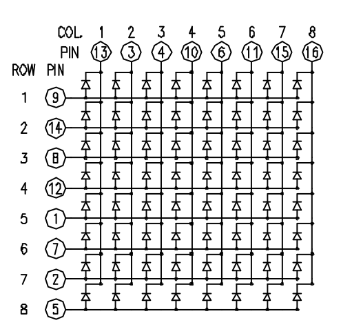
Since an image is worth a thousand words, here's an example of LDM-24488NI: a 64-led matrix

enter image description here

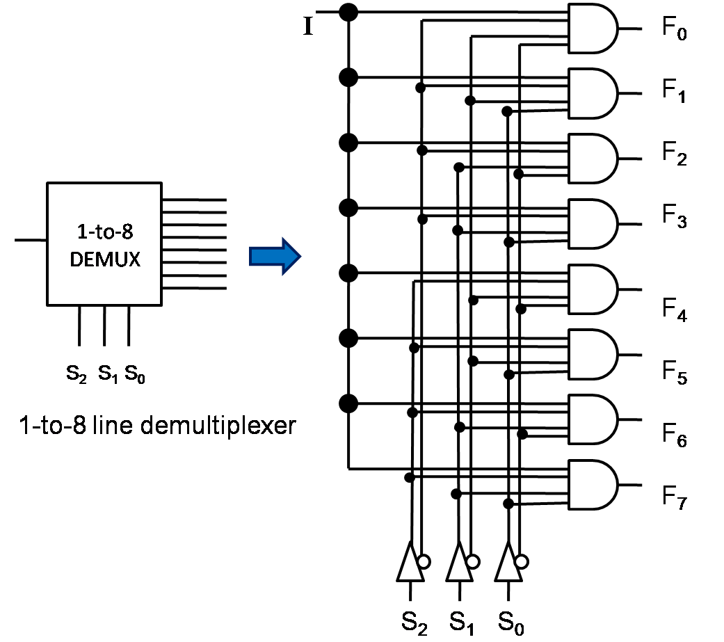
For your application you will need one such matrix for LEDs, and another one for sensors, requiring a total of 32 IO pins. Since your RPi doesn't have that many, you will have to use 1-to-8 demux to select individual rows and columns:

enter image description here

For LEDs, you can use demultiplexers for both rows and columns, since you only need one led at a time. For sensors, I'd recommend using a demux for rows and individual lines for columns, to be able to detect multiple active sensors in one row. That will bring the required pin count to 17 pins, which an RPi can handle.

\$\endgroup\$
12
\$\begingroup\$

Yes, multiplexing as you describe is a common way to address arrays of things.

The trickiest part will be dealing with the analog nature of the light sensors. CdS LDRs (light-dependent resistors) are probably the best in this case because they are sensitive, cheap, and produce a large easily-measurable response over the human lightness range. Electrically, they are resistors, with the resistance decreasing in brighter light.

It would simplify the multiplexing if you use a micro that has 8 analog inputs. That means half your mux is built into the micro. You enable a row of LDR, and read the 8 column signals directly with the micro, for example.

Scanning 64 analog inputs sequentially can easily be done instantaneously in human terms with ordinary micros. Let's say you can take a new reading every 100 µs. That's "long", even for small and cheap micros. That means the whole board would be scanned every 6.4 ms, which is way faster than you can perceive a delay.

Multiplexing the LEDs is even easier since that is all done with digital outputs. Plenty of micros have well more than 16 digital outputs, so this is no problem. There is other stuff that will have to happen, and you'll use up pins faster than you may expect now, but a 64 pin micro should really be good enough, if not a 44 pin one.

I'd probably dedicate one micro just to handling the board I/O. This is optimized for having enough I/O pins, A/D inputs, and the like. It then interfaces to the main computation engine via UART. The protocol would look like "light up square 3,2" or "piece removed from square 5,4". This also allows a totally different hardware interface in the future as long as you keep the protocol the same.

\$\endgroup\$
7
\$\begingroup\$

For the LED's, the obvious way to do this is to have an output for each row and each column of the chessboard: a total of 8+8=16 pins. The anodes would be connected to the row wires and the cathodes to the column wire. For the LED you want to light you would make its anode wire positive (logic 1) and its cathode wire negative (logic 0), while maintaining the others in the reverse state (so the remaining LED's have neutral or reverse bias.)

I'm making an assumption here that the microcontoller gives suffciently high/low voltages for you to be able to bridge an LED from one to another. If that is not the case you will need a transistor or buffer for each line. With 5V supply it's tight, considering the LED drops about 2V and you want a reasonable voltage drop over your current limiting resistor (note you only need to install these in either the row lines or the column lines, not both.)

If your outputs are tri state (that is, in addition to logic 0 and logic 1, they can be set to a high impedance state, perhaps by temporarily configuring them as inputs) then you can get clever and use a 4x8 grid, with LED's connected in antiparallel pairs. It's important to set unused outputs to high impedance in this setup, otherwise unwanted LED's will light up.

In either case, you will have to think about the current draw, and whether it is acceptable to risk the possibility of a software error lighting all LED's in a row at once (which if not accounted for, could overcurrent that row line of the microcontroller.)


The case of the sensors is more complicated. I'm going to assume you use resistive sensors, though phototransistors are not necessarily guaranteed to conduct in only one direction.

You can use the same 8 row outputs that you use to light your LED's, but you're going to need 8 column inputs dedicated to sensing. You will, no doubt, have seen circuits for keypads like this. Bear in mind that these are only designed to have one key pressed at a time. If the user presses 1,3,7 and 9 together, the keypad is unable to detect if the user releases any one of these four keys because there still exists a current path through the other three switches.

A solution used on musical keyboards (which are designed to have more than one element of the matrix conducting at a time) is to have a diode in series with each and every switch.

Another solution would be to buy four 4-to-16 decoder ICs with open collector outputs (or open drain if using MOSFET IC's)such as this: http://www.unicornelectronics.com/ftp/Data%20Sheets/74159.pdf Open collector means that the outputs of the IC will only sink current, not source it. Thus you can connect 16 sensors to 16 outputs of the chip, and common the other ends together with a pullup resistor (you would connect your ADC here too). You bring one output low (conducting) and the other 15 remain high (nonconducting.) This is in contrast to the standard logic output, where the other 15 outputs would be pouring current into the common point.

The input to these IC's is 4 bit binary to select one of the 16 outputs, but they also have an extra input to enable/disable the chip. Thus you could potentially have an array of 64 open collector sinks, connected to 64 sensors, with the other ends of the sensors all commoned to a single pullup resistor and analogue to digital converter. You would need a total of 8 outputs on your microcontroller for this: four to take the 4-to-16 select signals (common to all four chips) and four to take the enable signals (one for each chip.)

EDIT: 3 to 8 decoders (also called 1 of 8 = 1 line out of 8) seem to be more available than 4 to 16, but 8 IC's is a lot more messy than 4. Another type of IC which could be useful is the octal counter (and its more common cousin the decade counter, which can be configured as an octal counter by connecting its ninth ouput to the reset line.) These require a serial pulse to advance from one output to the next, so the would need less I/O pins on the microcontroller than the decoder IC's. They typically have additional inputs for reset and enable. There are also IC's called shift registers, which are available in two types: one for converting series to parallel, the other for converting parallel to series. Finally, there are buffers, which you can put between your Rasberry Pi and your chessboard so the Pi doesn't get destroyed in event of overcurrent. All of these can be useful in multiplexing circuits.

\$\endgroup\$
3
  • 1
    \$\begingroup\$ You mention shift registers -- they could be used for the LED outputs as well. Another counter plus an 8-bit shift register that can tristate could drive the whole array with barely more than two or three pins, if they're fast enough to avoid visible flickering. \$\endgroup\$
    – hobbs
    Commented Dec 11, 2015 at 1:46
  • \$\begingroup\$ @hobbs I don't think flickering is an issue as OP only wants to light one or two LED's at once. Even tristate isn't really necessary if you just have one straight and one inverting decade / octal counter / shift register to drive the LED's. 3 pins is perfectly achievable: common reset, column advance, row advance. That may be the way to go - save all the other pins for the more difficult problem of the sensors. \$\endgroup\$ Commented Dec 11, 2015 at 2:25
  • \$\begingroup\$ For the LEDs the MAX7219/7221 LED Driver could be used as well. This will reduce the number of inputs to 3 - clock, data, latch. \$\endgroup\$
    – jnovacho
    Commented Dec 11, 2015 at 10:28
4
\$\begingroup\$

Multiplexing is indeed a common practice.

There are a couple of ways you can get more out of your raspberry pi pins

One is to use a chip to do some of the heavy lifting for you. For example, if you have 8 inputs and 8 outputs to read the board's state, you can use a counter, to raise the 8 inputs up one at a time. You will need 2 pins on the Arduino for this - one to reset back to the first pin, and one to "go to the next row". You just saved 6 pins!

Saving 6 pins might not be enough - lets see where we can go from here: If you re-arrange your 8x8 grid into a 16x4 grid, you can use something like http://www.instructables.com/id/16-Stage-Decade-Counter-Chain-Using-two-4017-Chi/?ALLSTEPS (ignore the top half, the two lines coming down from the top to the bottom are your "reset", coming from the top-left, and the "go to the next row", which is called CLK, for clock, here). You can now count the 8 on the left-half of the board, followed by the 8 on the right half of the board; connect column A and E, B and F, C and G, and D and H together.

Congratulations, you now have two output pins (reset and clock), and 4 input pins, for a total of 6 - that saves 10 pins! Note that the raspberry pi does not have analog to digital converters, so you will need some extra work for that.

Now for the LEDs. You already have a controlled power supply (the two decade counters) - lets reuse those. Put your 64 LEDs from your 16 supply pins, via a resistor (each LED MUST have it's own resistor!), to 4 other rails (same layout as above: AE, BF, CG and DH). Connect these 4 rails to via 4 transistors to 4 pins, and put all pins to "high" - since both sides of the LED is now at 5 volts, the LEDs will be off. Then, when you want to light an LED, make sure your two decades are in the right position (as if you were reading the sensor on that square), set one of the 4 rails to low. Current should now flow from the "high" from the decade counter, to the "low" in that specific rail. Hey presto, the light comes on! Give a little delay, then turn it back off before you change the decade counter again. You can easily blink several lights, so long as only one light is on at a time.

If you do want more control, you can use something like a TLC5940 chip - http://playground.arduino.cc/Learning/TLC5940 - each chip can set 16 LEDs (so you'd need 4 of these) to a brightness level from 0 (off) to 1024 (full on), so you can fade individual LEDs in and out, with great control. From memory, these need about 4 pins, and they can be daisy chained, so 4 digital pins (one of which must be PWM - these have "~" symbol next to the pin) will control any number of LEDs.

Good luck!

\$\endgroup\$
2
  • \$\begingroup\$ It's RPi, not Arduino. \$\endgroup\$ Commented Dec 11, 2015 at 11:44
  • \$\begingroup\$ My apologies, you are right. Almost everything I said still applies, so I have made some minor edits, to make it work \$\endgroup\$ Commented Dec 12, 2015 at 5:29
0
\$\begingroup\$

I don't think you will need a LED at the upper right corner. A sensor in the middle as you mention would be enough. The Tricky part will be the code for the chess board. Imagine you have a chess board. The row will be indicated as 'alphabet' and the column indicated as 'number'.

So first you need a program to program the type of piece at the initial position. Later on, when you move your pieces, the code will generate the piece initial location to the final location. That will reduce your input by half.

\$\endgroup\$
1
  • 5
    \$\begingroup\$ Maybe I didn't explain the well … the LEDs are not meant for reading in the current state, they are meant for showing which move the computer wants to make. So, user makes move: Brightness sensors tell the software what the used did. Software calculates its next move, and blinks two LEDs, user moves the piece, and then it's the human's turn again. \$\endgroup\$
    – Golo Roden
    Commented Dec 10, 2015 at 15:58

Your Answer

By clicking “Post Your Answer”, you agree to our terms of service and acknowledge you have read our privacy policy.

Not the answer you're looking for? Browse other questions tagged or ask your own question.