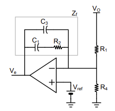
I'm trying to design a type II compensator for my LT1249 boost PFC stage but I'm not sure on how to place the zero and poles frequencies using a typical error amplifier:
I have a working LTspice simulation, how to obtain the open loop bode plot, considering this is a AC/DC system how would I be able to obtain a ? Should i use a DC equivalent state space model instead?
Regarding the frequencies of the poles and zero is there a rule on how they should be placed? It's hard to obtain the gain of the current loop since I'm struggling to understand fully the LT1249 schematic, so I was hoping to set the compensator without having the need for the current gain

