9
\$\begingroup\$

I need to measure 0v to 40mV as accurately as possible with the 10-bit ADC on an Arduino Nano. I only need approximately one sample per second.

I plan to hold the AREF pin at 40mV above ground, properly shield everything, use low-pass filters in hardware and software and use a properly smoothed power supply.

  • What sort of accuracy am I likely to get?

  • What else could I do to improve the accuracy?

\$\endgroup\$
1
  • \$\begingroup\$ Check the datasheet of your controller for available band gap reference voltages. Then design an amplifier that amplifies the maximum signal to little under that reference voltage. \$\endgroup\$
    – jippie
    Commented Apr 17, 2013 at 12:40

3 Answers 3

9
\$\begingroup\$

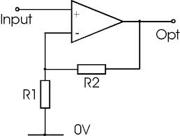
There are better experts on the Nano's ADC than me but I'm sure it will have some problems so I would suggest an amplifier for sure. I would recommend an op-amp running from 5V (or whatever the nano uses) and 0V. The op-amp will need rail-to-rail capabilities on input and output and be configured in non-inverting mode with gain that converts 40mV to full-scale on the nano.

enter image description here

If full scale is (say) 3V, you'll need a gain of 3/0.04 = 75. This means R2/R1 = 74 (75 minus 1).

R1 will be happy to be 100 ohms and therefore R2 will be 7400 ohms (7k5 in parallel with 560k gives 7k401 which will hopefully be near enough. The op-amp is only required to run at slow speeds having read your question and there are several devices that will suit. Hold fire while I post the answer and take a look...

The AD8538 looks suitable and so does the AD8628 but there are probably several more that easily fit the bill

\$\endgroup\$
5
  • 1
    \$\begingroup\$ Full scale is Vcc, but providing a reference voltage on the AREF pin allows a lower full-scale reference as required. However, the amplification is still desirable, as AREF below 1.0 Volts doesn't work AFAIC (no documentary evidence, just some problems I faced). \$\endgroup\$ Commented Apr 17, 2013 at 12:42
  • \$\begingroup\$ Why not more common E12 resistors? The exact ratio isn't too important, as long as you know to compensate it. Eg. 12k÷150 = 80 or 33k÷470 ≈ 70. Of course this is the case for 3V output voltage, which is probably not optimum. \$\endgroup\$
    – jippie
    Commented Apr 17, 2013 at 12:43
  • \$\begingroup\$ @jippie I agree totally but my answer "suggests" how to put resistors in parallel and I wasn't sure whether the OP knew this. He got an extra answer for free!! \$\endgroup\$
    – Andy aka
    Commented Apr 17, 2013 at 12:46
  • \$\begingroup\$ +1 for the op amp suggestion, the AD8538 is a personal favorite, especially in the SOT23 package - no meaningless pins, excellent thermal behavior. \$\endgroup\$ Commented Apr 17, 2013 at 12:51
  • 1
    \$\begingroup\$ @AnindoGhosh - 20 months on. ATMega328 datasheet does not seem to say anywhere in its 650 pages what range of values are valid for EXTERNALLY applied Aref voltage BUT all of the many graphs where it is mentioned have a lower limit of 1.8V :-(. Vcc may be >= 1.8V and AVcc may be Vcc-0.3V so as low as 1.5V is legal. Using the internal 1.1V bandgap reference gives a lower max ADC voltage. Lower external V_ARef MAY be legal but its not certain. \$\endgroup\$
    – Russell McMahon
    Commented Jan 4, 2015 at 12:16
1
\$\begingroup\$

I originally didn't plan to add this as an answer, but it seems to important to let it drown somewhere in comments.

It's the thing of the greatest importance, to resort to the datasheet of your microcontroller. And if I'm correct about Arduino Nano having ATmega 168, here is the datasheet. Electrical characteristics is a section you have to know about and check the things there first.

The point is: minimal reference voltage is 1.0V - you can see it on the page 311. You'll have to amplify your signal at least by a factor of 25 to get reasonable accuracy, scaling up to minimal voltage reference.

Now the best choice of elements I know (though I barely know the topic) would require a low-noise operational amplifier, able to operate as rail-to-rail like @Andyaka pointed out, preferably running at your supply voltage. Then I think that the best choice of the voltage reference is the internal one. Even though they may vary between devices, I think that the stability should be most reasonable. Moreover, your choice of resistors should lie in lower resistances rather than higher, as they are more noise resistant. Don't forget about they stability over time and temperature changes!

The best configuration of amplifiers might vary - noninverting amplifier might be good to start with, but it's high input impedance might not work well with your signal (although it should be OK).

\$\endgroup\$
4
  • 1
    \$\begingroup\$ Why would a high input impedance not work well with the signal? The Arduino GPIOs in input mode are all high input impedance, by the way, as also most ADCs. \$\endgroup\$ Commented Apr 17, 2013 at 12:45
  • 1
    \$\begingroup\$ @AnindoGhosh If the signal source has to be loaded to measure and it isn't done properly. I can't tell anything about nature of OP's signal. I think that the suggestion in my post was too harsh on the amplifier - it probably shouldn't happen, but high input impedance is a thing I think it's better to be aware of. \$\endgroup\$
    – TNW
    Commented Apr 17, 2013 at 12:52
  • \$\begingroup\$ I believe loading a signal source if needed is a well-known science, and equally, designers typically strive for a high input impedance and a low output impedance. Hence my downvote on that unqualified statement. \$\endgroup\$ Commented Apr 17, 2013 at 12:54
  • 1
    \$\begingroup\$ @AnindoGhosh I think it might be better to assume that the person knows less than more (especially that 40mV ref made me suspicious). I wanted to point out that the choice between inverting and noninverting amplifier is not only depending on whether we can allow polarity change. \$\endgroup\$
    – TNW
    Commented Apr 17, 2013 at 13:03
-4
\$\begingroup\$

You should use an amplifier for maximum accuracy.

\$\endgroup\$
3
  • \$\begingroup\$ Thanks - but why? Wouldn't extra stages increase noise and inaccuracies? What sort of amplifier circuit would give best results? \$\endgroup\$
    – Jayy
    Commented Apr 17, 2013 at 11:43
  • 1
    \$\begingroup\$ I suppose that low-noise operational amplifier in noninverting configuration could do, as long as you use stable resistors to maintain voltage gain. \$\endgroup\$
    – TNW
    Commented Apr 17, 2013 at 11:50
  • 3
    \$\begingroup\$ For someone who reprimands other users for not supplying information, this sure is a bare answer. Could you maybe add some schematics or additional detail? \$\endgroup\$ Commented Apr 17, 2013 at 16:37

Your Answer

By clicking “Post Your Answer”, you agree to our terms of service and acknowledge you have read our privacy policy.

Not the answer you're looking for? Browse other questions tagged or ask your own question.