I've been trying to learn VHDL recently and came across the following tutorial for an ASK modulator: https://surf-vhdl.com/implement-digital-ask-modulator-vhdl/
I tried writing a testbench for this modulator so that I can see it generate a modulated output but I am not getting anything from the output port of the dut. Here are my assumptions:
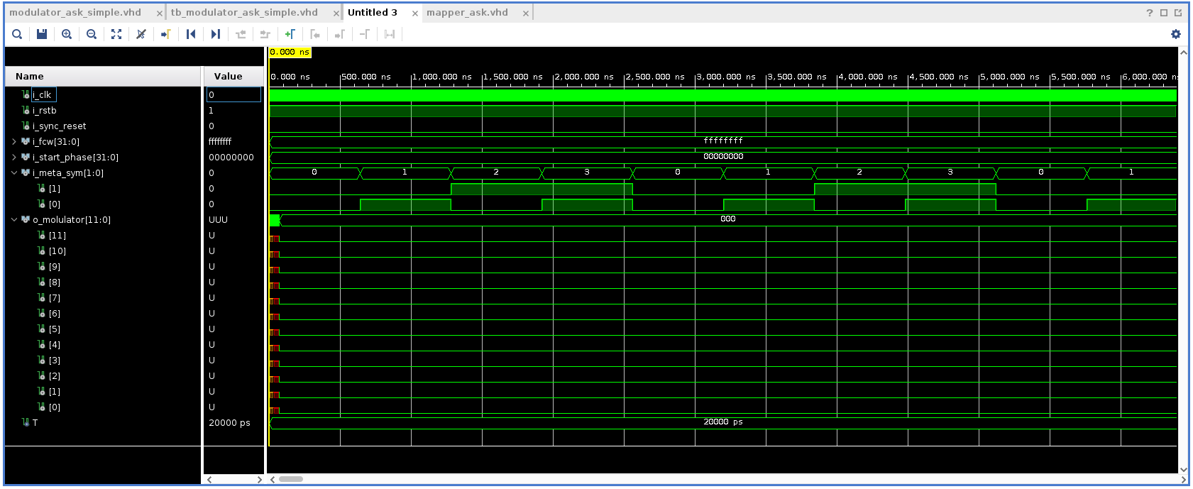
i_meta_symrepresents the 4 possible messages I can use from:00,01,10and11- I can run two processes concurrently, one to generate clock signal, and another to change
i_meta_sym - I have used 32 clock cycles for changing between the message symbols (640ns)
Here is the result of my simulation for reference.
and my testbench code:
library IEEE;
use IEEE.STD_LOGIC_1164.ALL;


entity tb_modulator_ask_simple is
--  Port ( );
end tb_modulator_ask_simple;

architecture arch of tb_modulator_ask_simple is
    constant T : time := 20 ns;

    signal i_clk : std_logic; -- input
    signal i_rstb : std_logic; -- input
    signal i_sync_reset : std_logic; -- input
    signal i_fcw : std_logic_vector(31 downto 0); -- input
    signal i_start_phase : std_logic_vector(31 downto 0); -- input
    signal i_meta_sym : std_logic_vector(1 downto 0); -- input
    signal o_molulator : std_logic_vector(11 downto 0); -- output


begin

    dut: entity work.modulator_ask_simple port map (
        i_clk => i_clk,
        i_rstb => i_rstb,
        i_sync_reset => i_sync_reset,
        i_fcw => i_fcw,
        i_start_phase => i_start_phase,
        i_meta_sym => i_meta_sym,
        o_molulator => o_molulator
    );

    i_rstb <= '1';
    i_sync_reset <= '0';
    i_start_phase <= (others => '0');
    i_fcw <= (others => '1');

    -- continuous clock
    process
    begin
        i_clk <= '0';
        wait for T/2;
        i_clk <= '1';
        wait for T/2;
    end process;

    process
    begin
        i_meta_sym <= "00";
        wait for 640ns;
        i_meta_sym <= "01";
        wait for 640ns;
        i_meta_sym <= "10";
        wait for 640ns;
        i_meta_sym <= "11";
        wait for 640ns;
    end process;


end arch;
Additionally, I couldn't work out how to connect the carrier wave from the dds_sine source so that I can also see what it (carrier) looks like during simulation.

