0
\$\begingroup\$

I need to design a circuit that can control the amount of current that an LED draws (the LED is rated from 0 - 500 mA). The current drawn by the LED should be controlled in the code that the Teensy 4.1 is running, by probably varying the duty cycle of a PWM signal (since the Teensy 4.1 does not have a DAC).

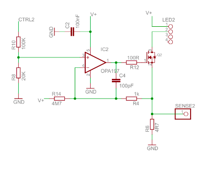
I came across the following circuit here:

enter image description here

The circuit uses a control voltage (I figured that from the "CTRL2" terminal shown) and a sense resistor (SENSE2) to control the current flowing through the LED, that's pretty much all I know about the circuit.

I have been unable to construct this circuit since I do not know how exactly the sense resistor is doing its thing here.

How does this circuit work? What is this type of LED driver (current regulator) called? That would help me Google it at least.

Is it possible to control the same circuit by converting the PWM signal to an analog voltage and giving that to CTRL2 or is there a simpler way to achieve what I want to do?

\$\endgroup\$
3
  • 1
    \$\begingroup\$ "do not know how exactly the sense resistor is doing its thing"—the higher the current through the sense resistor, the higher the voltage across it, which will have an effect on the inverting input of the op amp. Is that what you're looking for? \$\endgroup\$ Commented Mar 24, 2023 at 18:35
  • 3
    \$\begingroup\$ While you can design this from scratch if you really want, there are many inexpensive LED current driver ICs that can easily be controlled from an Arduino. Do you really want to reinvent the wheel? \$\endgroup\$ Commented Mar 24, 2023 at 18:36
  • \$\begingroup\$ You are halfway done. You just need to put a 2nd-order low-pass-filter between your PWM output and CTRL2. You may notice that a duty-cycle of zero probably not turns the LED totally off. Also when starting with increasing duty-cycle the lowest few values might actually not change the brightness. Both may be ok for your application. Where did you get that circuit from? The R14/R4 divider looks is placed differently as I though it should be - need to think about it a bit... \$\endgroup\$
    – datenheim
    Commented Mar 24, 2023 at 19:21

2 Answers 2

2
\$\begingroup\$

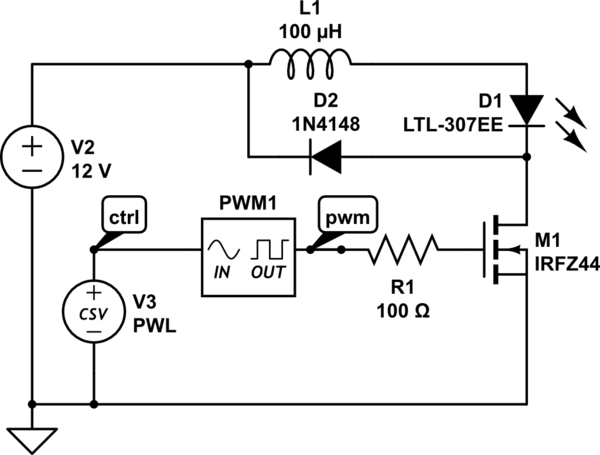
Unless the OP needs a smooth DC current through the LED, it would be much better to keep the PWM to drive the MOSFET. However, the analog current regulation circuitry would not work. You would need to provide a filtered feedback to an analog input, which would be used to adjust duty cycle. And there would need to be a current limiter to control the peak current during the PWM ON cycles.

A more efficient way to accomplish this is with a series inductor to limit the peak current, although this can get a bit tricky to avoid continuous conduction mode runaway at high duty cycles.

schematic

simulate this circuit – Schematic created using CircuitLab

Voltages

LED current

In order to show how the LED current can be made smooth, I changed L1 to 5 mH, and I applied three levels of PWM: 40%, 60%, and 80%. The PWM frequency remains 20 kHz. Here are the current waveforms. Oddly, for some reason, the PWM signal and the control signal (PWL) just show some mV of random noise.

LED current

\$\endgroup\$
1
\$\begingroup\$

Ignoring for the moment that CTRL2 can vary, the circuit is a constant current driver. Feedback from the sensing resistor, R6, is inverted by the opamp and this in turn drives Q2 in such a way as to keep SENS2 constant. As the voltage on the '+' input of the opamp changes with CTRL2, then the voltage across R6 has to change to match and hence the current through the LED.
Look up "source follower" (aka common drain) and "constant current circuit".

\$\endgroup\$

Your Answer

By clicking “Post Your Answer”, you agree to our terms of service and acknowledge you have read our privacy policy.

Not the answer you're looking for? Browse other questions tagged or ask your own question.