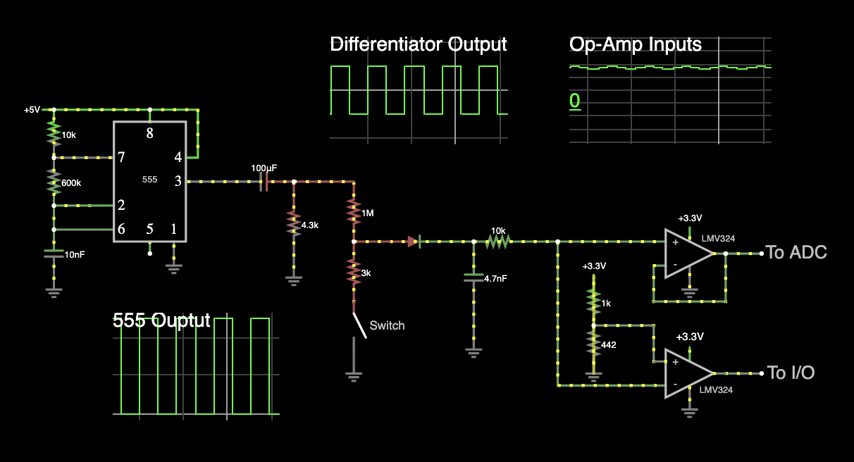
There is a lot of impedance between the differentiator output and the op-amp inputs, due to the 1MΩ resistor, and it rises to near infinity when your rectifier is reverse biased (which is half of the time).
Any impedance to ground (or elsewhere) following the diode, including the oscilloscope probe, will change the circuit's behaviour markedly.
When the diode is forward biased, the 4.7nF capacitor charges up to some voltage, but during the other half-cycle it doesn't have any path via which to discharge; the reverse-biased diode isn't a route for current, the op-amps' super-high input impedance isn't either. The voltage at the top of the capacitor can rise, but has no way to fall again, and it will tend to remain more or less constant. That is, until you connect the oscilloscope probe, which provides a discharge path to ground, and suddenly the potential there "pops into life".
Worse still, during this state of having no current path via which to charge/discharge, the input bias current of the op-amp becomes a significant contributor to the state of charge of the capacitor, further compounding your troubles.
It seems to me that the goal of the 4.7nF capacitor is to "smooth" the half-wave rectified signal, acting as a kind of "peak detector". If that's true, then you must provide a discharge path for that capacitor, allowing the voltage across it to discharge slowly between peaks.
Here's what I would do to fix these issues:
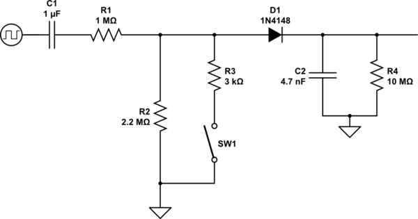
simulate this circuit – Schematic created using CircuitLab
I added R2 to allow the differentiator to operate properly even when the electrodes are out of water. R4 is the resistance your scope probe "accidentally" placed across C2, allowing C2 to discharge.
With this setup, you are operating the op-amps with inputs very close to zero, without a negative supply. In other words, those inputs could fall outside acceptable bounds. I propose a few more changes:
Use a biasing network to provide an "average" potential somewhere between the supplies of 0V and +5V, about which the signal can swing, to keep all op-amp inputs happy.
Reduce the source impedance of the "water" signal, so that currents become significant compared to the op-amps' input bias currents. Then the influence of the op-amps themselves on the signal being measured can be ignored.
Employ an active rectifier to "peak detect", while simultanuously buffering the signal for any following stage. It will also remove the annoying 0.7V drop across the rectifying diode.
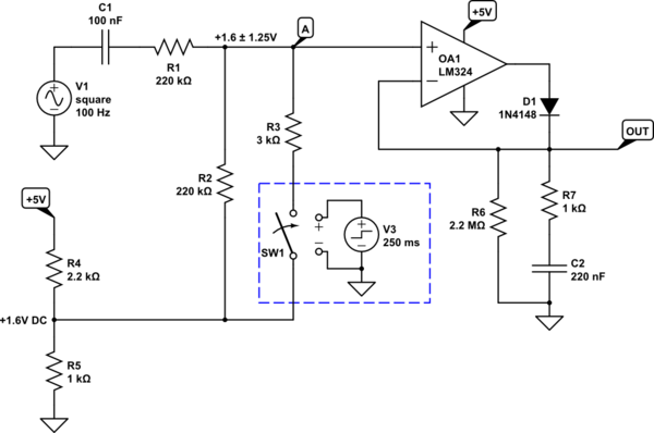
Here it all is, with component values chosen to work at around 100Hz:
simulate this circuit
R4 and R5 produce a low-ish impedance source of +1.6V, which will be the "no water" average potential about which our op-amp input will fluctuate.
R1 and R2 divide the 555 output by 2 (to become 2.5V peak-to-peak), and together with C1 they form your "differentiator", so we obtain a signal +1.6 ± 1.25V at node A. The presence of water will lower the net resistance of the system R2 and R3, and the amplitude of oscillations at A will reduce, but the average remains +1.6V.
The water probe is connected between this +1.6 ± 1.25V waveform, and the fixed +1.6V source, and so the voltage across it is 0 ± 1.25V. Consequently current through it is symmetrical above and below zero, with an average of zero.
Measuring node A is the active peak detector, which you can read about here. R7 is there to limit the current demand from the op-amp's output while it is charging C2. C2 is performing the same role as the 4.7nF capacitor in your own circuit, but is no longer drawing current directly from your "water signal"; instead the op-amp is doing the heavy lifting, and that signal is almost completely unloaded.
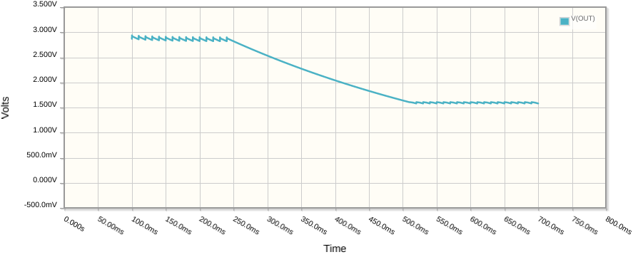
Here's the output OUT when switch SW1 is closed (simulating electrode immersion in water) after 250ms:
This is current through the switch (water):
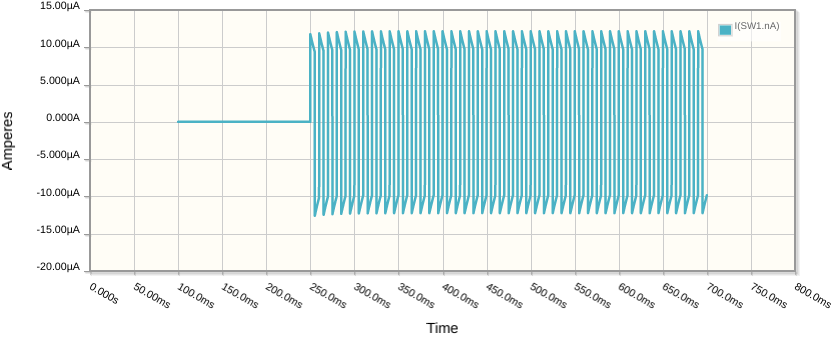
As you can see, due to C1, it quickly settles to become symmetrical about zero, proper AC.

