0
\$\begingroup\$

What would be the best way to drive 3 high-power RGB LEDs with one 18650 battery? The LEDs are 3 W a piece. Forward voltage is 3.2 V, forward current 350 mA per color.

I would like to use a mini RGB controller but they don’t function well at low voltage or practical with a large resistor. Can anyone give me basic direction on what components I should use to design a board with basic functionality to change colors and maybe brightness? I’m very sharp with ESP dev boards, I just need direction on hardware for LED controls.

\$\endgroup\$
7
  • \$\begingroup\$ One very easy solution is to set up to 5v and then power a normal RBG controller with that. You could design something more clever to waste less power, but it sounds like you're looking for a simple solution. \$\endgroup\$ Commented Mar 27, 2023 at 1:02
  • \$\begingroup\$ I’m trying to conserve space as well. I’ve tried using a boost converter to bump the voltage higher but it makes the leds flash and the voltage drop is to much. \$\endgroup\$ Commented Mar 27, 2023 at 1:26
  • \$\begingroup\$ You can get single ICs that contain the boost converter and the RGB controller all in one, so very compact. That'd take more design work though. Alternatively you could buy a better boost converter that works correctly (or design one yourself) and pair with an off the shelf controller. Lots of options, choose whatever works for your problem. \$\endgroup\$ Commented Mar 27, 2023 at 1:30
  • \$\begingroup\$ boost converter [makes the LEDs] flash and the voltage drop is to much sounds exceeding some current limit somewhere - if controlled individually and up to rated current, that's 3.15 A and more than 8 W - net. \$\endgroup\$
    – greybeard
    Commented Mar 27, 2023 at 1:30
  • \$\begingroup\$ The more I looked into it, I’ve learned that I need a constant current device. The only thing I’ve found that’s constant current is a step down converter which doesn’t help either. Where would you recommend I shop for quality electronics other than Amazon? \$\endgroup\$ Commented Mar 27, 2023 at 1:39

1 Answer 1

1
\$\begingroup\$

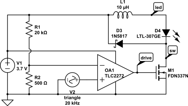
schematic

simulate this circuit – Schematic created using CircuitLab

This is a circuit that should provide a smooth current through the LED using a PWM signal. I was unable to get the proper PWM duty cycle to achieve continuous conduction mode. But this should be able to power your LEDs.

\$\endgroup\$
4
  • \$\begingroup\$ (to achieve continuous conduction mode increase frequency, inductance (current down), or duty cycle(current up.)) What is the difference to using a square generator where now there is triangle+comparator? \$\endgroup\$
    – greybeard
    Commented Mar 27, 2023 at 7:04
  • \$\begingroup\$ I tried that and for some reason was unable to achieve CCM. Maybe I had the wrong values, but I think it's due to some peculiarities in the simulator. It seemed to work in another answer. There i think I was able to get the voltage to PWM device working properly. \$\endgroup\$
    – PStechPaul
    Commented Mar 27, 2023 at 18:23
  • \$\begingroup\$ Here are some successful simulations Only thing greatly different is power supply 12V and not 3.7V. electronics.stackexchange.com/a/659055/316329 electronics.stackexchange.com/a/660188/316329 \$\endgroup\$
    – PStechPaul
    Commented Mar 27, 2023 at 18:37
  • \$\begingroup\$ Fixed PWM, into a stiff load like an LED, from a variable supply, in CCM, is every ingredient in a recipe of disaster. Current mode control however is perfectly suitable. \$\endgroup\$ Commented Jul 14 at 23:18

Your Answer

By clicking “Post Your Answer”, you agree to our terms of service and acknowledge you have read our privacy policy.

Not the answer you're looking for? Browse other questions tagged or ask your own question.