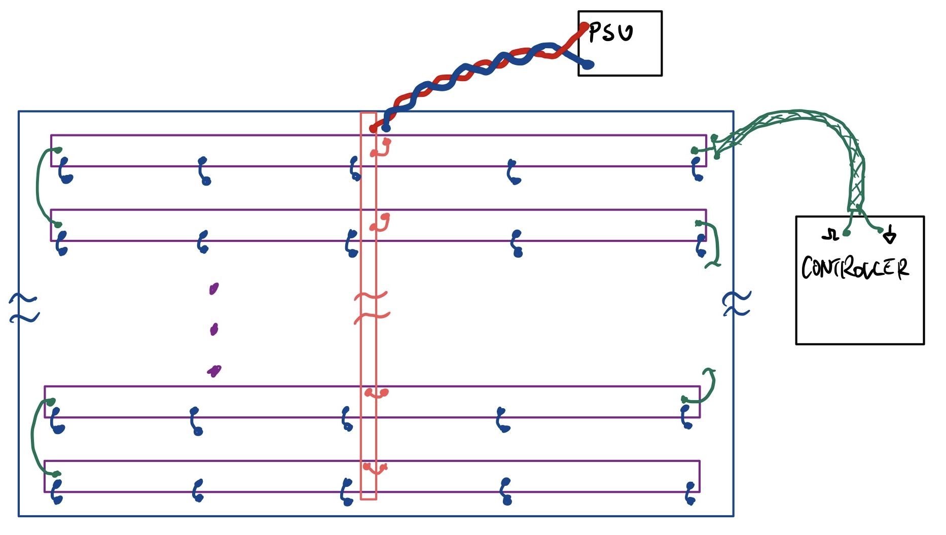
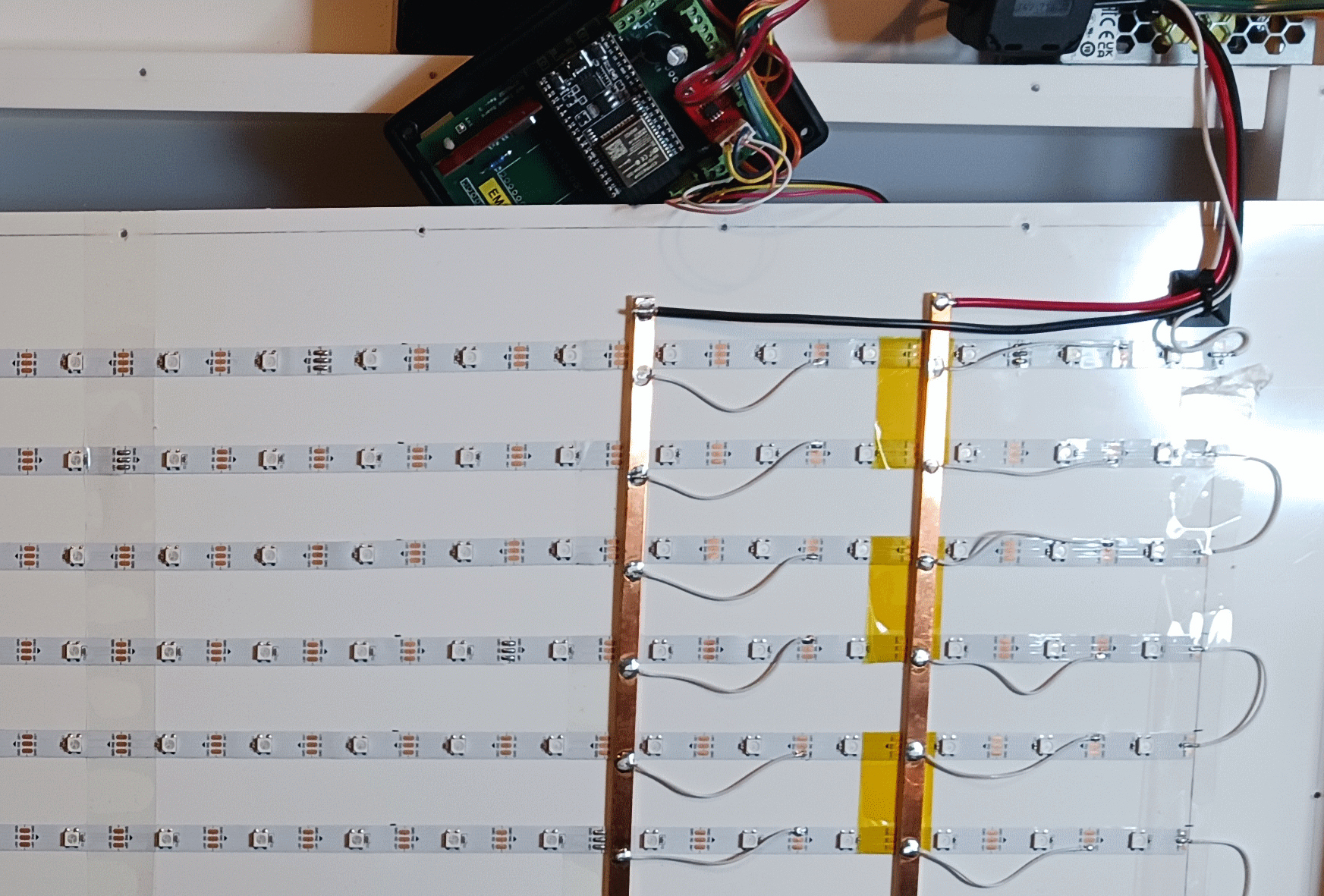
I'd start by adhering the LED strips on a thin conductive backplane, say made out of galvanized steel or stainless. Then locally connect several ground points on each strip to the backplane, using short (1" max) wires. That backplane constitutes a GND return. I'd say the jumpers should be no farther than 6" apart along each strip. If that works, you can always spread them further apart.
VCC should still be distributed using the vertical bus, put in the middle of the length of the strips, not at the end. The bus should be glued to the backplane using e.g. thin double sided tape, and the jumpers from the bus to the VCC points on the strips should be short - 1" max.
Connect a dedicated LED power supply between the backplane and the vertical bus. This should be a "floating" power supply with DC output that is not earth-referenced, and should not be used to power anything else but the LEDs. This is very important to avoid ground loops. Twist the wires going from the power supply to the display.
Now you have two options:
Run data in a daisy chain. With the backplane and tight power distribution as above, this may now work well enough, EMI-wise. Connect the MCU to the first LED strip using a shielded cable. Connect the shield directly to the backplane right next to where it connects to the LED strip, and also to the GND plane on the controller that generates the control signals.
Verify that there are only two external connections that connect to the backplane: the shield of the control signal, and the (-) side of the LED power supply.
Run data separately to each strip, using a thin shielded cable for each connection from the controller to the strips. The controller will have to generate several signals in parallel, or it can activate those connections individually one after another. One shield should be terminated on both ends. Shields from other cables can be terminated on the controller end only.
Verify that there are only two external connections that connect to the backplane: the shield of either one control signal or all of them, and the (-) side of the LED power supply. The choice between connecting one shield or all shields to the backplane may have some effect, and it's hard to tell which way will be better at the moment.
The LED power supply should not connect anywhere but to the backplane and the busbar. The wires should be either in a common shield, or twisted together.
The daisy chained option would look like this:

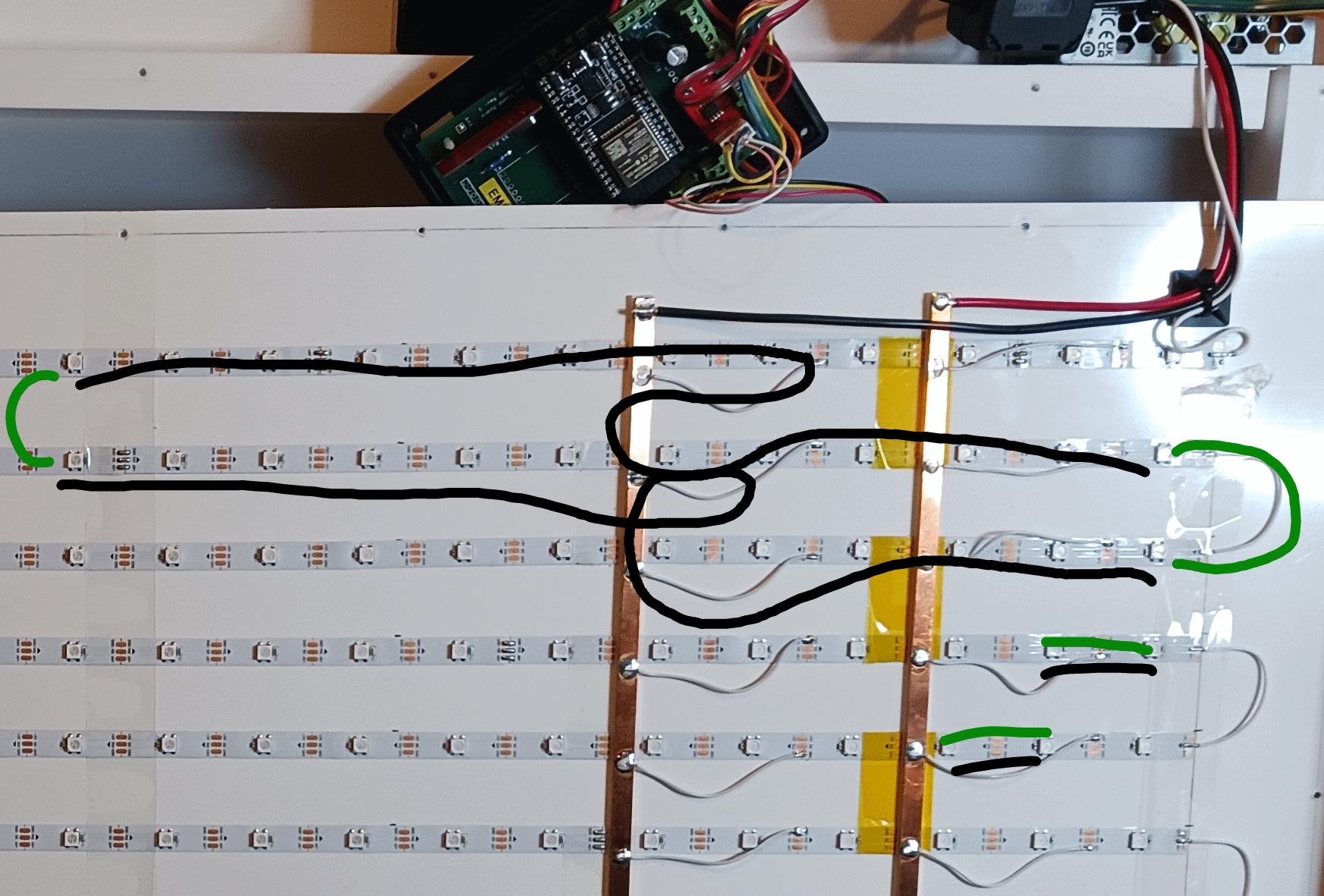
With this approach, there is a reasonable return path for the control signal current - it will flow on the backplane directly under each strip.
The wires that daisy chain the strips must be laying flat on the backplane - use tape to hold them down for testing. For production, the backplane can have pairs of holes through which you'd loop a zip-tie to retain those cables. Similarly you can strain-relieve the PSU wires and the shielded control cable.
I have had a similar project a couple years ago, and I didn't even bother with a single backplane. The design had two CNC-cut aluminum sheets it was sandwiched between. The thicker one was a backplane and a mechanical mount. The thinner one on the front was a shield, with a nice cutout for each LED. The shield had push-in threaded studs on standoffs, to maintain distance between the shield and the backplane. The backplane had mating holes. Nuts with captive lock washers were used on the back of the backplane to capture the shield hardware.
The shield had a distributed connection to the backplane via the mounting hardware.
We also ran copper tape on conductive backing around the outer seam between the shield and the backplate. It wasn't necessary just to pass EMC, but it did improve things so it was left in place following the "less EMI is better" mantra.
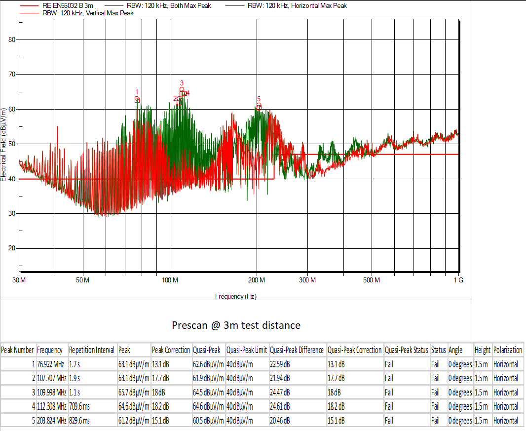
 The scan looks like:


