10
\$\begingroup\$

How can I design a circuit that can be charged to around 10kV (somewhere between 5 and 20kV is fine) from two AA batteries (~3V)?

I am going to draw about 20mA over a high resistance load for a short amount of time, around 20 to 50msec. It is okay if it takes the circuit a while to reach the 10kV output voltage, as to not draw too much current from the battery while charging the circuit.

When discharging, the output current will be current limited to a maximum of 20mA.

\$\endgroup\$
10
  • 1
    \$\begingroup\$ Do you mean milliamps (i.e., 200W) or microamps (more like 0.2W)? \$\endgroup\$
    – Dave Tweed
    Commented Apr 18, 2013 at 12:46
  • 1
    \$\begingroup\$ (a) That's a potentially lethal voltage/current combination. (b) That's also 400W, no mean amount of power. (c) I'd start from various DIY tesla or spark projects: rmcybernetics.com/projects/DIY_Devices/homemade_tesla_coil.htm \$\endgroup\$
    – pjc50
    Commented Apr 18, 2013 at 12:49
  • 1
    \$\begingroup\$ How much voltage droop can you tolerate during the discharge cycle? This will determine the size of the capacitor you need. Then you can figure out how long it would take a couple of AAs to charge it. Even once charged up, it will require several minutes between dicharges to recover -- and that's assuming 1A draw from the batteries, which is a lot. \$\endgroup\$
    – Dave Tweed
    Commented Apr 18, 2013 at 12:58
  • 6
    \$\begingroup\$ @LeonHeller: 200W * 50ms = 10J. A pair of AAs should be able to do that 100s of times. \$\endgroup\$
    – Dave Tweed
    Commented Apr 18, 2013 at 13:01
  • 1
    \$\begingroup\$ @bjarkef, I gave you an upvote to cancel that because this will have a solution. But just re-reading the question (without comments) you probably should edit to include you're charging a cap and cycle time doesn't matter much. It does read a bit like you're expecting it to deliver 20mA @ 10kV which even for a short time would be impossible without the cap. \$\endgroup\$
    – PeterJ
    Commented Apr 18, 2013 at 13:25

4 Answers 4

12
+50
\$\begingroup\$

How can I design a circuit that can be charged to around 10kV (somewhere between 5 and 20kV is fine) from two AA batteries (~3V)?

The difficulty in this question is understanding some of the requirements so I'll address this first because without answers it's debatable that this can be answered properly.

Firstly, is the load going to be applied once the output cap is charged to the required voltage? If the load is present all the time during the "charging process" then the power required is very much more than some of the answers and comments anticipate. I don't think a solution is achievable if load is always connected so I'm assuming it isn't.

The OP also says "the output current will be current limited to a maximum of 20mA". Is this a requirement of the solution or something that is external to this question? This needs an answer but for now I'm assuming it isn't required in the solution.

Proposal - A transformer is going to be needed that steps up the 3V (nominal) supply to probably about 800Vp-p. With a split primary and two N channel MOSFETs, an effective primary p-p voltage of about 12V(minus a bit of loss) should be attainable. The secondary will therefore have between 70 and 80 times the turns of the primary: -
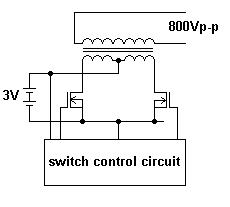
enter image description here

I think this is reasonable do-able and at a decent switching frequency of up to 1MHz. From experience i don't believe a transformer with more than about 100:1 stepup is practical - just too lossy.

The MOSFETs are not going to be common-place items. I think they'll need to be something like 60V rated and have an on-resistance down close to the 10 milli-ohm area. Low drain capacitance is also a requirement. More detail later as I think about it and simulate it.

Driving the MOSFETs is also tricky. It's likely that they'll need to be driven with 10 or 12V gate voltages and this means that a small boost convertor will be needed to power the switch control circuit from the 3V. This isn't a big issue. I did consider having the booster provide the power to the transformer primary but this is a significant source of inefficiency and I believe a higher turns ratio on the transformer is the best idea.

There is detail in the switch controller that needs to be ironed out like having it perform a gradual soft start to build up the o/p voltage preventing the batteries from "collapsing" under the "pressure".

The final stages would be several ( less than 10) cockcroft walton multipliers and I think the diodes used will need careful selection. More detail later - I have one in mind but I left my notes at work and my memory is letting me down!

Sorry I haven't got the full details yet but of course the question is "how can I design a circuit" meaning how can the OP design the circuit.

Mondays additions Here is the basic circuit I came up with - it generates a bit over 6kV and I decided to go for 40V rated FETs in the end because I limited the back emf with 18V zeners: - enter image description here
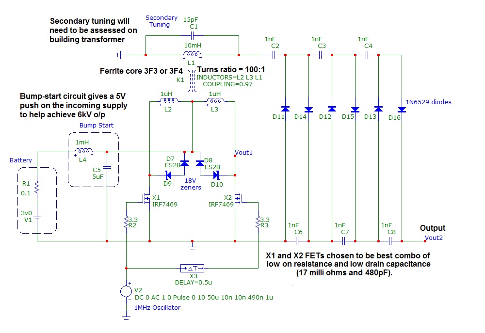
Here is the output after applying the battery. Lower display is the FET drain voltage and current taken from the battery thru 0.1ohms in series:-
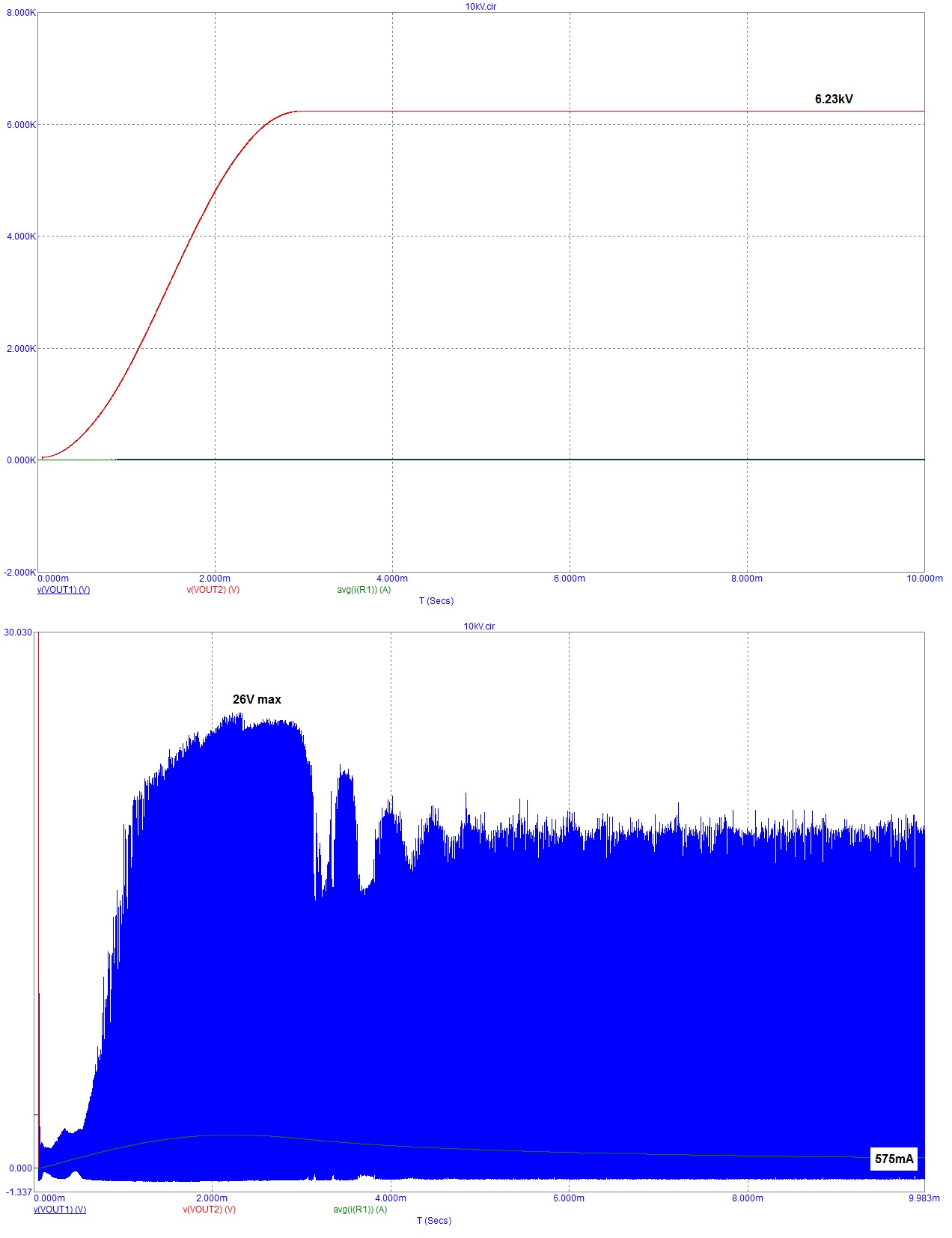
enter image description here

To overcome the battery's inherent resistance I used a 1mH inductor and 5uF capacitor to act as a voltage booster during power up. The best way of doing this would probably be to charge a decent sized capacitor (1000uF) up to 5V over an allowable time period and let it act as the boost to achieve +6kV output, then return to the 3V battery for trickling energy into it to keep the output at 6kV. Alternatively, as the OP wants only a 20ms period of high voltage at the output, the 1000uF may suffice to keep things reasonably steady for that period and if not increase to 10,000uF.

Not shown is the boost convertor that powers the 1MHz oscillator. There are several devices from Linear technology that would perform this function. 12V is needed for driving the gates.

Small Print The secondary of the transformer needs care in winding to keep capacitance below about 10pF. I'm not going to go into this but suffice to say, the output circuit relies on secondary resonance and so a trimmer cap of 20pF should be used to optimize output voltage without over-resonating it and causing large inefficiencies in power transfer.

Bear in mind that this could easily kill you if you do not take care. Be warned.

\$\endgroup\$
8
  • \$\begingroup\$ Which Monday? :-) \$\endgroup\$ Commented Jun 14, 2013 at 14:56
  • \$\begingroup\$ @AnindoGhosh are you in a hurry dude LOL \$\endgroup\$
    – Andy aka
    Commented Jun 14, 2013 at 15:02
  • 2
    \$\begingroup\$ @AnindoGhosh it's a heavy cross you have to bear ;)... This monday of course (hopefully) - I've spent too many years pulling the wool over manager's eyes to know ya can't BS engineers! \$\endgroup\$
    – Andy aka
    Commented Jun 14, 2013 at 15:09
  • 1
    \$\begingroup\$ Why do the MOSFETs need more rating than the 3V supply? \$\endgroup\$
    – pjc50
    Commented Jun 14, 2013 at 18:48
  • 2
    \$\begingroup\$ @pjc50 Firstly, when one fet open circuits, the other one pulls the other side of the primary down to 0V and this immediately forces 6V onto the drain of the releasing mosfet. Secondly there will never be 100% coupling which means a spike and to keep efficiency and switching speed high I'm not wanting to use snubbers. I reckon there will be a complex looking back-emf that could easily hit 30V peaks so I'm being a tad cautious maybe with 60V BUT 40V is too close for comfort and there are more 60V devices than 50V ones. \$\endgroup\$
    – Andy aka
    Commented Jun 14, 2013 at 18:55
4
\$\begingroup\$

How critical is your voltage and duration?

What you are describing is VERY similar to a common points/coil ignition circuit from a car engine. Car battery supplies current to the primary of a ferocious transformer (the ignition coil). Breaker points periodically turn the current hard on and hard off, the sharper the rise and fall the better. The magnetic field collapsing induces a REALLY high voltage in the secondary, which goes through the distributor (essentially a motor-driven rotary switch) to the sparkplug (spark gap).

\$\endgroup\$
1
  • 5
    \$\begingroup\$ The "ferocious transformer" made me laugh! Not merely aggressive, eh? \$\endgroup\$ Commented Apr 18, 2013 at 18:26
4
\$\begingroup\$

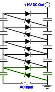
The traditional way of getting this for low charge levels is known as a capacitor diode bridge circuit AKA voltage multiplier. You'd use the batteries to generate a AC waveform which you then feed into the end of this multiplier circuit.

enter image description here

The higher the AC voltage the fewer stages you need to get to 10KV.

Be careful though, this circuit can store charge in the lower caps. Also dielectric absorption can rear it's head and you can find charge across caps that you though were discharged.

You want 20ma in 20 ms => 400 uC of Charge. (\$ Q=I*t\$) if you pump to 12KV and drop to 10 KV during discharge you have a change of 2KV.

to supply that charge you need:

\$ Q = C*V = C* \Delta V \$

\$ C = \frac{Q}{\Delta V} = 0.2 uF\$

so in the picture above (5 caps) you'd need 1uF caps each capable of 2KV sustain and a 2KV AC waveform. As first order estimate. Hopefully this gives you enough to do your own calculations (and hopefully not kill yourself)

I even found a version inside of our favourite schematic tool circuitlab.

[circuitlab]mh9d8k[/circuitlab]

\$\endgroup\$
6
  • 4
    \$\begingroup\$ This kind of charge pump multiplier is not appropriate in this case due to the very large step up ratio. This circuit needs one stage per mult factor with perfect diodes. Figure 1.5 V lost in diode drops per stage, so each stage only adds 1.5V. You'd need over 3300 stages to get to 5 kV. \$\endgroup\$ Commented Apr 18, 2013 at 17:54
  • 1
    \$\begingroup\$ @OlinLathrop you'll have to read a little more closely. the excitation in my -simple- example is 2KV. \$\endgroup\$ Commented Apr 18, 2013 at 17:58
  • 3
    \$\begingroup\$ But then how does that help? He is asking how to make 5-10 kV from 3 V, and your answer is to start with 2 kV. If he knew how to make 2 kV, he could probably make 5 kV. \$\endgroup\$ Commented Apr 18, 2013 at 18:30
  • \$\begingroup\$ @OlinLathrop 1 KV to 2Kv is very simple with a very small transformer, 10KV not so much. As to how does it help the 1.5V drop on the diode is irrelevant. But there are trade offs, he can easily just use 1KV and double the stages up. \$\endgroup\$ Commented Apr 18, 2013 at 18:38
  • 5
    \$\begingroup\$ I still consider this a non-answer unless you show how to get this 2 kV to start with. \$\endgroup\$ Commented Apr 18, 2013 at 19:15
0
\$\begingroup\$

I am thinking a multi-staged diode-based voltage multiplier (driven by a square wave/oscillator) that could charge a (large) capacitor. Use something like a JFET to dump the capacitor through the primary side of a step-up transformer - somewhat gradually, with a sharp cut-off to collapse the secondary to high voltage on the kick-back.

I think this is sort of how a car's ignition coil works.

I don't know how long the discharge would be - but discharge time could be extended with a capacitor, tuned for the attached load. (If exponential decay of the voltage is okay).

\$\endgroup\$

Not the answer you're looking for? Browse other questions tagged or ask your own question.