2
\$\begingroup\$

I'm trying to build a 48-54 V linear regulated power supply for a CNC motor controller and I'm looking for some suggestions for a beginner. I have very little experience when it comes to circuit design so please bear with me.

Ideally I'd like to use the stepdown transformer I already have which came from a Denon audio receiver. It has dual secondaries in series for a total of 74 V AC and is rated for 1000 W. I'm open to other options if they are somewhat basic.

I would like to be able to adjust the voltage from 48 V DC to 54 V DC.

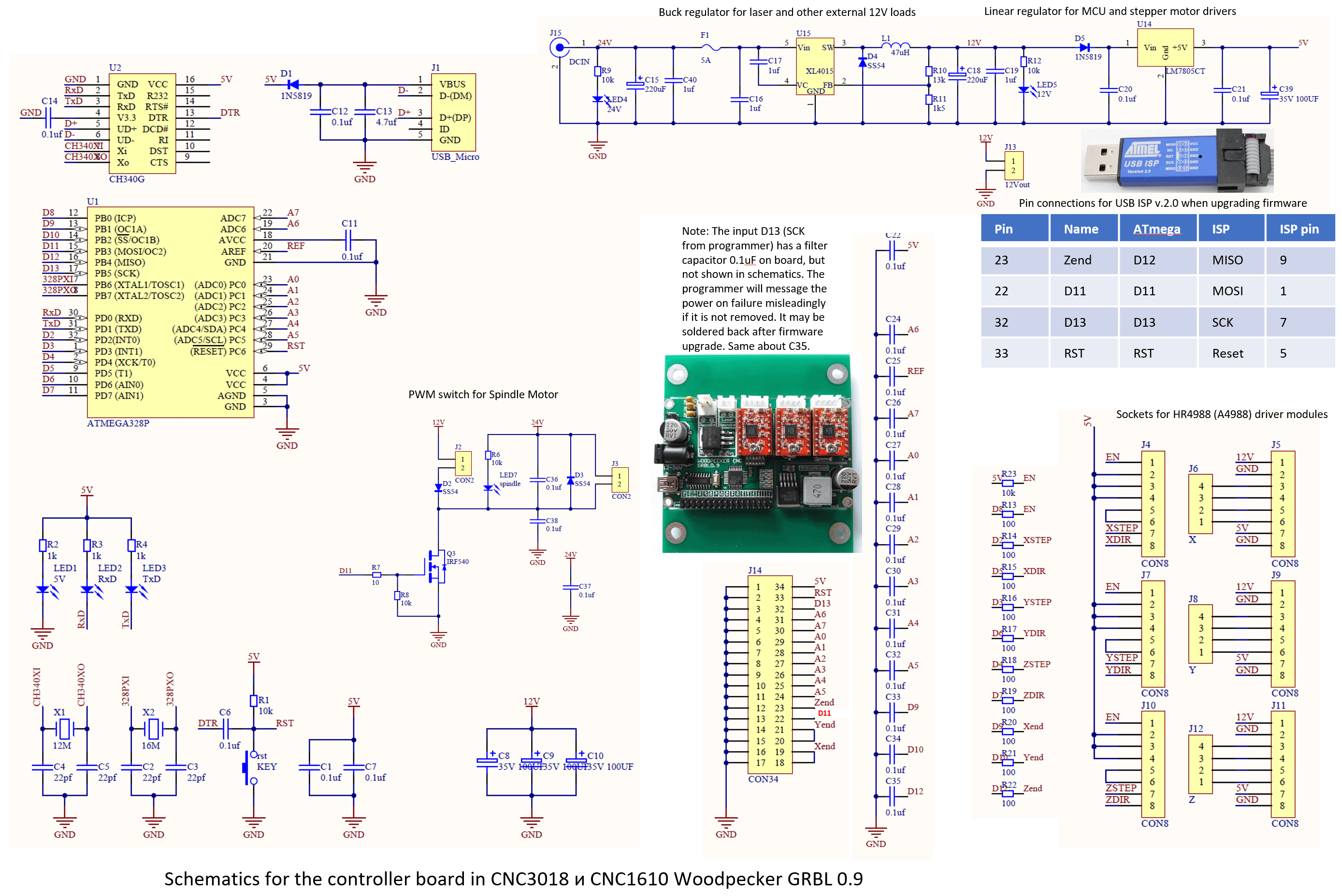
This is the motor controller. It uses the 5 V or 24 V PWM signal from the CNC controller to an external motor controller. Mine will use the 12 V PWM signal to drive the gate of the external motor controller.

CNC controller:

3018 cnc controller schematic

I am using a 48 V DC motor which uses 300 W.

\$\endgroup\$
12
  • \$\begingroup\$ It is unclear how your proposed 48 VDC power supply connects to the 24 VDC spindle motor controller and the 12-48 VDC spindle motor. \$\endgroup\$
    – PStechPaul
    Commented Apr 2, 2023 at 5:43
  • \$\begingroup\$ @PStechPaul the motor controller described in the link below will connect the proposed power supply to the VDC motor controller. pedja.supurovic.net/36v-cnc-spindle-motor-driver/?lang=lat \$\endgroup\$
    – Infernoman
    Commented Apr 2, 2023 at 5:46
  • \$\begingroup\$ So you are not using the controller shown in your question's schematic? The one in your link seems much simpler, and designed for 36 volts. Do you plan to push it further to 48 volts? \$\endgroup\$
    – PStechPaul
    Commented Apr 2, 2023 at 5:54
  • \$\begingroup\$ The schematic in my question is the original CNC controller which only supports 24 V. The link I posted is an external motor controller which uses the pwm output of the original CNC controller to allow for a higher voltage supply to the motor. I am planning to use the 12 V pwm output from the CNC controller instead of the 5 V or 24 V pwm. And I plan to use 48 V instead of 36 V for the motor. \$\endgroup\$
    – Infernoman
    Commented Apr 2, 2023 at 6:08
  • 2
    \$\begingroup\$ So you will also need a 24 VDC supply for that? And what about the titanium plating supply? You need to put all this extra information in your question, and not in comments. \$\endgroup\$
    – PStechPaul
    Commented Apr 2, 2023 at 6:25

1 Answer 1

1
\$\begingroup\$

Your proposed linear solution is simple at low power but at 1000 W there will be a lot of heat to get rid of if you use the 74 Vac series connected scheme. If you use separate rectifiers on each 37 VAC winding then you will be close to your desired 48 VDC. Why not lash the circuit up using some big say 10 mF 63 VDC or better electrolytic caps and measure the no load output on the DVM. Double check the fine print of the drive specs for max allowable DC volts in. Now you may not need a linear reg at all, if you do it will not have to drop much voltage so it wont waste much power meaning heatsinking will not be a drama.

\$\endgroup\$
6
  • \$\begingroup\$ So the dual rectifiers would share the center tap connection and one 37 V to each. Then run the outputs of the rectifiers in parallel? \$\endgroup\$
    – Infernoman
    Commented Apr 2, 2023 at 5:51
  • \$\begingroup\$ (<350 W load, 1kVA transformer available. And the transformer needs to be derated depending on "rectification" details.) \$\endgroup\$
    – greybeard
    Commented Apr 2, 2023 at 9:06
  • \$\begingroup\$ @greybeard. I have two LN25XB60 Rectifiers available. The filter capacitors are 56v 10000 uF which were originally paired with the transformer. \$\endgroup\$
    – Infernoman
    Commented Apr 2, 2023 at 9:21
  • \$\begingroup\$ @Infernoman You wouldn't hear the best advice: use an SMPS. (Adjustment range typically 48.6 V to 59.5 V @a 54 V.) I think Autistic's advice the 2nd best: Lash up a basic rectifier circuit and see how far that gets you (Don't let the open circuit voltage irritate you). If you can't separate the secondary into independent windings, you aren't screwed for good: make the centre tag your GND, connect the AC sides of both bridges, but use the + terminals of each, only, leaving the - unconnected. In any case, go separate paths & connect as far to the load as feasible for better current split. \$\endgroup\$
    – greybeard
    Commented Apr 2, 2023 at 12:07
  • \$\begingroup\$ @greybeard With my limited knowledge I don't think I would be able to build an SMPS. But if you can suggest a basic SMPS circuit I'd be willing to give it a try. Tomorrow I'll be separating the secondaries, and adding a second rectifier then I'll post the results. \$\endgroup\$
    – Infernoman
    Commented Apr 2, 2023 at 12:47

Your Answer

By clicking “Post Your Answer”, you agree to our terms of service and acknowledge you have read our privacy policy.

Not the answer you're looking for? Browse other questions tagged or ask your own question.