I'm building something that is going to have Li-Ion batteries so I'm trying to learn how a battery charger actually works. I've been looking over the datasheets for the BQ2000 and the BQ2954. I will say preemptively that I am only looking at ICs which have through-hole variants on purpose. I'm seeing the obvious overlap is that the example designs in the datasheet are just modified buck converters.
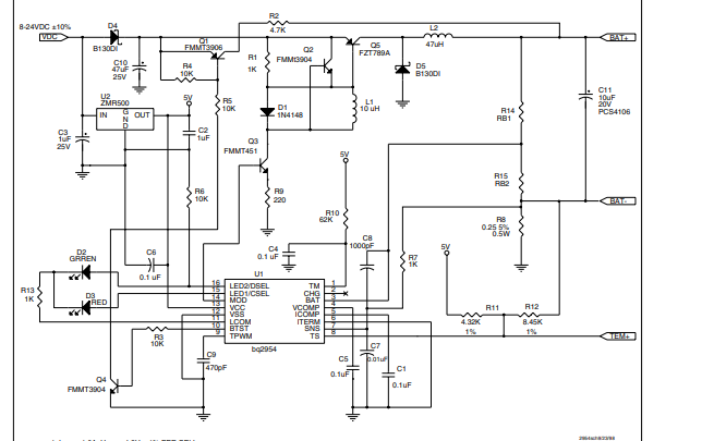
Here is the example from the BQ2954 datasheet

The actual current path to the battery goes through a PNP using drive circuitry that I somewhat understand to keep on and off times fast.
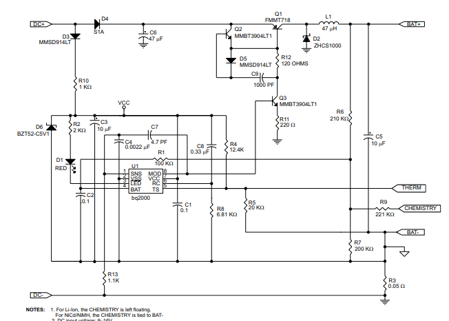
Here is the example from the BQ2000 datasheet

It's similar but there is no pullup from PNP base to emitter. I simulated this and it works, and I somewhat understand the idea: NPN for a quick discharge, but I do not understand this BQ2000 version. How is the PNP base being biased before any control happens? What exactly is the diode-capacitor doing? I know this is more Buck control theory than battery charging but that brings me to my second question:
The BQ2954 has two external pins for compensation: Vcomp and Icomp. The BQ2000 has no such pins. Is there either:
A way to apply this compensation to the IC that does not have these pins?
or
A more generic IC type that I could be using instead of these specific battery charging ICs?
It seems like the only benefit is basically an integrated time-out that I could potentially do in software with a microcontroller.
Any experience using battery charging ICs is helpful.
