0
\$\begingroup\$

This is a followup to Injecting a UART TX output signal to an audio input pin, without messing up the audio?

The preferred solution for TX was a tristate buffer, which makes sense, until we recognize that the buffer's output can see negative voltages (audio). The high-Z is not high-Z when there's a negative voltage, it conducts (probably across internal body diodes).

Is there a clever solution to this? I don't have dual voltage rails, and haven't found an analog switch or buffer that can handle a negative voltage on its output, unless I have a negative rail. I'd rather not add a negative voltage rail just for this, or a relay, if it can be avoided.

The "dirty" approach is to put a large-ish resistor at the output of the buffer, hopefully much larger than the output resistance of the audio source, which will minimize current flow on the negative wave, and perhaps distortion. I'm not crazy about this, as it also drops the UART TX voltage some due to the series resistor and the audio input circuit forming a divider. A workaround might be to output a 5V TX and let the system divide this to 3.3V.

Is there a clever way to solve this problem robustly?

\$\endgroup\$
1
  • 1
    \$\begingroup\$ What is your required baudrate and do you need active 3.3 V at the output or can you live with just pulling the line down to GND while the receiver has a pull up resistor? \$\endgroup\$
    – Jens
    Commented Apr 10, 2023 at 17:55

1 Answer 1

1
\$\begingroup\$

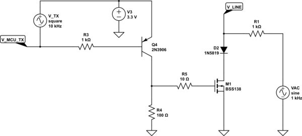
The idle state of a raw MCU UART signal is high. If the intended receiver has an internal pull up resistor to either 3.3 V or 5 V, it will be sufficient to pull the line down to GND in the active TX state.

A Schottky diode in series with a NMOSFET can pull down the line to around 450 mV, which should be seen as low by the receiver, the high level is defined by the supply voltage of the receiver and not relevant here.

As long as you don't send data, the line can be fed with AC audio signals up to 20 V without much distortion. There is just the capacitive load of the diode and the not conducting MOSFET, something between 100 pF and 1 nF.

Since you didn't specify the source impedance of the audio signal, it is hard to say if this capacitance is a problem here.

If the AC signal has a very low source impedance, say below 100 ohm, you may introduce problems if you accidentially send data while the audio signal is present.

To detect a receiver, you can use an R/C low pass filter connected to the line. If you measure a DC voltage above 1 V, a receiver is connected. A bipolar AC signal would sum up to 0V behind the filter.

schematic

simulate this circuit – Schematic created using CircuitLab

\$\endgroup\$
8
  • \$\begingroup\$ Interesting idea - can I count on a UART receiver to have said pullup? I hadn't thought this was a convention, but maybe it is. \$\endgroup\$
    – rspaudio
    Commented Apr 12, 2023 at 15:23
  • \$\begingroup\$ I don't have control over the audio source, but I would imagine 100pf and 1nf would be tolerable. Maybe I can replace with some lower-capacitance devices to be safe. I can't guarantee the user won't try to send data with an audio source connected. As long as it doesn't damage anything we can live with this. The ability to detect a receiver is a clever addition as well, so the user doesn't have to select it. But since this is part of a balanced line input (RX is the other side) I have to try to make this as "invisible" as possible, and making impedance equal. \$\endgroup\$
    – rspaudio
    Commented Apr 12, 2023 at 15:30
  • \$\begingroup\$ Yes, the internal pullup resistor of an UART receiver is typically activated, but I would add one with lower impedance (<= 1 kohm) because you want to use pluggable, longer wires and need to add some ESD protection diodes on the receiver side. To be clear: I talk about raw TTL UART, not the RS232 levels of +/- 12V and hope I understood your application correct in this aspect. \$\endgroup\$
    – Jens
    Commented Apr 12, 2023 at 15:31
  • \$\begingroup\$ Thanks, yes, you have that correct. We do not (usually) have control over the receiver device, but would expect users to use typical USB to UART cables, such as from DTech and similar suppliers (FT232RL chip for example). (Yes, not RS232!) \$\endgroup\$
    – rspaudio
    Commented Apr 12, 2023 at 15:57
  • \$\begingroup\$ Some of them have internal pullup resistors, but most don't, because then they can accept either 3.3 V or 5 V signals. I would add a resistor between the unused TX pin and the RX pin as pullup. Since the application does not transmit, the TX pin is continuously active high. \$\endgroup\$
    – Jens
    Commented Apr 12, 2023 at 16:19

Your Answer

By clicking “Post Your Answer”, you agree to our terms of service and acknowledge you have read our privacy policy.

Not the answer you're looking for? Browse other questions tagged or ask your own question.