The question is in title. Why there is no ground pin on the 12V RGB header? The 5V ARG header which uses only 3 pins has a ground.
How does it work without a ground?
The question is in title. Why there is no ground pin on the 12V RGB header? The 5V ARG header which uses only 3 pins has a ground.
How does it work without a ground?
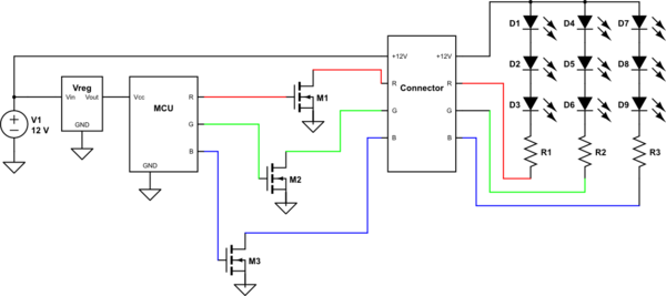
This is how it looks on the driver end. Whatever channel you want to drive, the R, G and/or B becomes ground with the help of a transistor, completing the circuit and allowing current to flow.

simulate this circuit – Schematic created using CircuitLab
EDIT: Added colors for clarity.
But there is a ground. Or actually, three grounds.
The three RGB wires are the grounds for the three LED colours.
The three colours just share a single +12V supply wire.
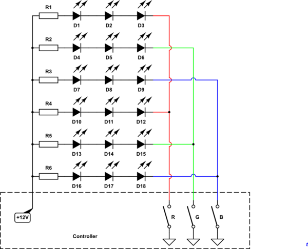
The anodes of all LEDs are connected to the 5V/12V. The cathodes of the LEDs go to the R, G, and B pins of the connector. The controlling device then connects the pins to ground to make the respective color light up.

simulate this circuit – Schematic created using CircuitLab
Figure 1. A manually switched controller for an RGB LED strip.
Closing the R, G or B switches will ground the last cathode of each string of R, G or B LEDs and cause them to light up. The switches can be replaced by transistors and these can be controlled by a microcontroller.
How does a 4 pin RGB connector work without ground?
The ground is provided by the control circuit.