This seems like a not-super-difficult problem to solve but I have read a ton on RC filters/LC filters/pi filters/bypass/decoupling capacitors/ferrite beads/chokes/bias tees and I still haven't been able to draw clear conclusions about what solution would be most appropriate for my use case, so I'd love to hear from some folks more experienced than myself what the best (or at least, a good) solution would be.
I am building a small box to verify intercom voltage and audio signal on analog partyline intercoms.
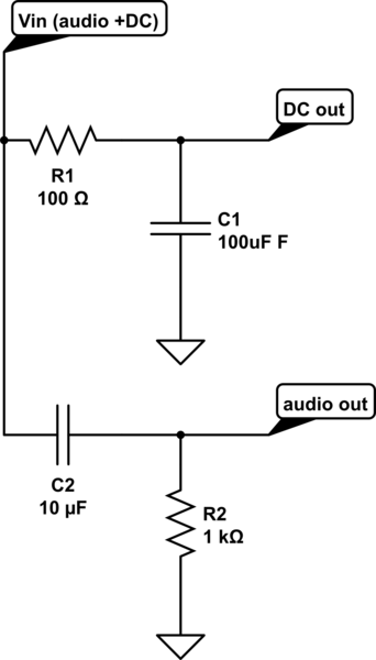
Coming in on XLR pin 2 I have a nominally 32 V DC signal with 75 Hz-20 kHz audio signal riding atop it, 2 V peak to peak. I simply need to separate these components for their respective uses. I've figured out blocking DC to pass the audio information to a headphone amplifier which is super simple (see circuit below). I think that filtering out the audio from the DC rail is also super simple, but I can't quite figure out which approach is the best fit.
The DC voltage will firstly be measured using this voltmeter (which draws up to 5-6 mA). Then it hits a regulator to power this headphone amplifier (which draws up to about 20 mA and accepts anywhere between 9 and 44 VDC). Whatever filtering method I use, it just needs to clean up the worst of the ripple from the superimposed audio signal to make a reasonably accurate measurement at the voltmeter; it's not a super demanding application that requires exceptionally clean power- the regulator should take care of the rest of it to feed the headphone amplifier circuit.
I don't want too much voltage drop across a resistor as in an RC filter; the whole point is to measure and display the original input voltage after all (although I may be able to accommodate a small voltage drop as I think the voltmeter has a small range of adjustment to calibrate it; how much I am not sure as the documentation is pretty basic for it). Dealing with resonance in an LC circuit seems like more trouble than it's worth if there is a simpler option of equal performance. I am looking at passive solutions as I want it to be as simple as possible. I am also unsure of the impacts of varying component values in these topologies even when identical filter responses are achieved.
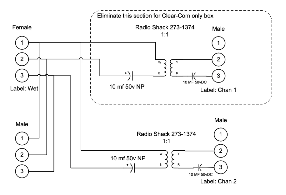
One more separate question: below is the circuit I am using to deliver audio without DC bias to the input of the headphone amplifier. The headphone amplifier in question does not have balanced inputs. Would I simply tie the pin 3 output of the below circuit to the audio ground on the headphone amplifier (as I know I cannot leave one side of the secondary of that transformer floating) while connecting the pin 2 output of this circuit to the left/right inputs of the headphone amplifier?
Thanks for any insight you can provide!


