0
\$\begingroup\$

Here is a configuration of MOSFETs which I believe allows for two different sources to supply power to the same load.

enter image description here

This diagram was originally found here.

The primary source is connected to the top pair of MOSFETs (labeled VCC_USB in the diagram.) The secondary source is connected to the bottom pair of MOSFETs (labeled VCC_USB_EDBG)

The source that is connected to the top pair of MOSFETs or the “primary” source, if it is connected, will supply the current for the load. The bottom pair of MOSFETs will act as diodes to prevent current from flowing from the primary source to the secondary source.

If the primary source is removed, because of their configuration, the bottom pair of MOSFETs will allow current to flow from the secondary source to the load and the top pair of MOSFETs will prevent current from flowing backwards.

Am I understanding this correctly?

This circuitry is for a lower voltage and amperage than what I want to use it for. I want to use it for 12VDC and 10-15 amperes of current. What MOSFETeds would be recommend to use for my configuration? I would prefer readily available low prices mosfets if possible. I was thinking that an FQP27P06would work. Could someone take a look and see if I am understanding it correctly and if those MOSFETs would work?

\$\endgroup\$

2 Answers 2

0
\$\begingroup\$

If you use fqp27p06, when transistor is ON, you'll have VGS=-12V, ID=15A & RDS will be ~0.07 ohm as per the datasheet (https://www.sparkfun.com/datasheets/Components/General/FQP27P06.pdf)

So, VDS drop will be ~1.05*2V (since you have 2 PMOS in series) = 2.1V. So, if you feed 12V, you'll get only 9.9V at the output. If this is ok, you can use it.

Edit: Also, you'd need a heat sink.

\$\endgroup\$
8
  • \$\begingroup\$ Yikes! I didn’t want that kind of voltage drop. Thanks for explaining! Could you recommend a better MOSFET? That I wouldn’t have that voltage drop? Thanks again! \$\endgroup\$
    – Georgia088
    Commented Apr 30, 2023 at 13:03
  • \$\begingroup\$ I'd not be able to give a recommendation. You can search on digikey, etc. Lower the RDSon, lower the drop. You can check if something is available based on the drop that is acceptable \$\endgroup\$
    – sai
    Commented Apr 30, 2023 at 13:41
  • \$\begingroup\$ @Georgia088, are both supplies same voltage? If they have a voltage difference of say >1V, the higher of the 2 will supply the load when both supplies are present. However, I am worried about the case where both supplies are equal. In that case, both supplies can be supplying power and it can lead to a stability issue if you are using the diode solution. \$\endgroup\$
    – sai
    Commented Apr 30, 2023 at 17:58
  • \$\begingroup\$ the voltages could be equal at some times. The system is actually a 4 LIFEPO4 cells wired in series to form a 12v nominal battery as one source. The second source is two 12v nominal lead acid batteries wired in series to form a 24v battery. The 24v battery will be connected to a buck converter to bring its voltage down to about 12v when it is connected. I would like for them to be connected to the same solar panels but with different solar chargers to keep both sets of batteries charged. The 24v pack will not always be connected to the system, but it could be the secondary source. \$\endgroup\$
    – Georgia088
    Commented May 1, 2023 at 11:35
  • \$\begingroup\$ My original intention was to use a MCU to monitor the two voltages. When the voltage from one source dropped below a defined threshold, the MCU would turn off an SSR (turning the primary source off) and turn on another SSR (turn ON the secondary source). I wanted the diode or mosfet configuration only as a "backup" in case the two SSR's malfunctioned and both stayed closed to prevent the two sources from becoming parallel sources. I was under the impression with the mosfet configuration, it was creating a "ideal diode" with a far less voltage drop than the Schottky diode. THANKS! \$\endgroup\$
    – Georgia088
    Commented May 1, 2023 at 12:02
0
\$\begingroup\$

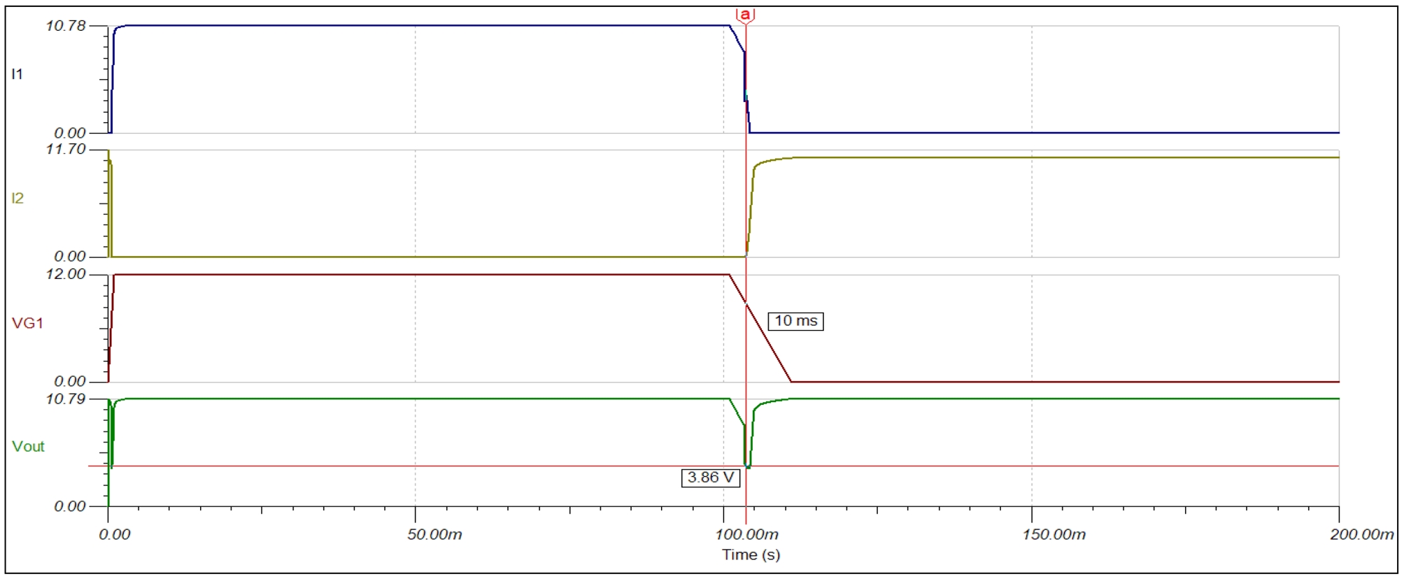
Yes, it works with 12 V input. It works quite well with fast input switching, with slow switching it will be transient at the output. The slower the input switching, the larger the output transient. Therefore, for high load currents, the value of the output capacitor (10 µF) must be increased. At a load of 10 A, the loss is already significant for the selected MOSFETs. enter image description here

EDIT:

Here is an example of a slowly varying (decreasing) input (VG1). The phenomenon is true for both inputs and in both directions. At an even slower change, the nature of the transient will be similar, only the gap at the output will be wider.

enter image description here

\$\endgroup\$
5
  • \$\begingroup\$ Thank you! I see that you show the same voltage drop. I was really hoping for a much less voltage drop. In my setup, I actually don’t care if both sources provide current to the load at the same time. I just don’t want the two sources (batteries) to be able to send current to each other. Would I be better off using a Schottky diode on each source to prevent back flow, as they typically have less voltage drop than what I suggested. Thanks! \$\endgroup\$
    – Georgia088
    Commented Apr 30, 2023 at 15:38
  • \$\begingroup\$ @Georgia088, using Schottky diodes is a better idea in that case. \$\endgroup\$
    – sai
    Commented Apr 30, 2023 at 16:09
  • 1
    \$\begingroup\$ If you use 30 A Schottky diodes, the losses will be half of this at a 10-15 A load (0.6 V). Another advantage is that there will be no transients during slow changes in the input voltage. Much more expensive MOSFETs would be needed here for a better result. \$\endgroup\$
    – csabahu
    Commented Apr 30, 2023 at 16:12
  • \$\begingroup\$ Thank you both! Sorry for my ignorance, but, can you explain what you mean by transients? \$\endgroup\$
    – Georgia088
    Commented Apr 30, 2023 at 17:52
  • 1
    \$\begingroup\$ When you have one supply present and ramp the other supply from 0 to 12V slowly, there could be a dip in the output because you may cut-off the first supply before the second one reaches 12V \$\endgroup\$
    – sai
    Commented Apr 30, 2023 at 18:01

Your Answer

By clicking “Post Your Answer”, you agree to our terms of service and acknowledge you have read our privacy policy.

Not the answer you're looking for? Browse other questions tagged or ask your own question.