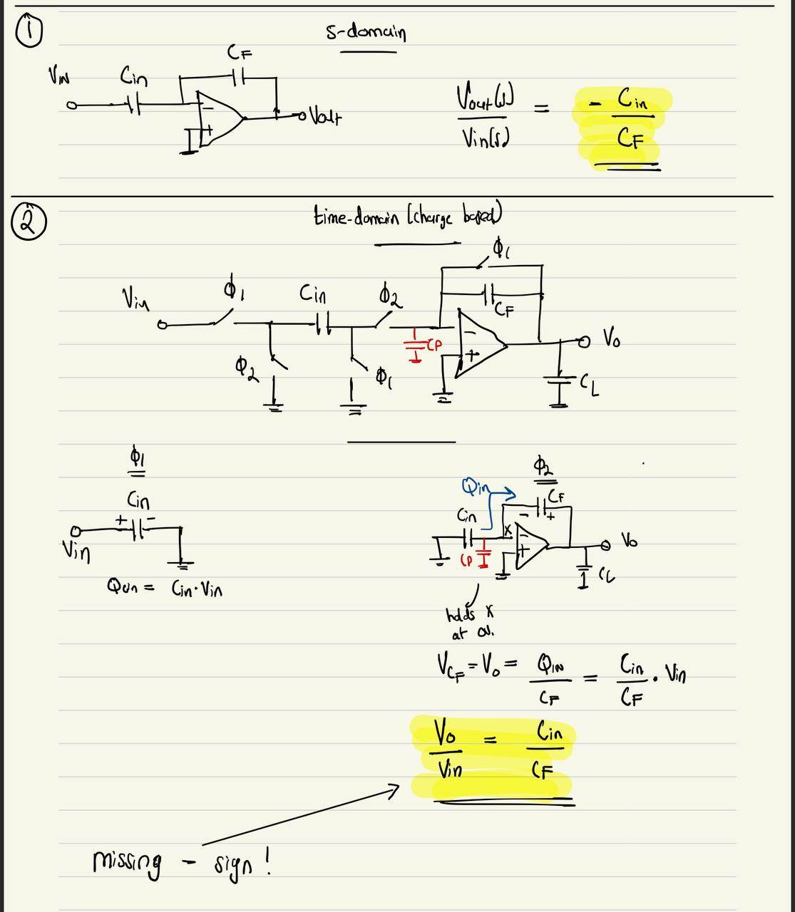
Can someone explain why in approach 1 of finding the transfer function, there is a negative sign but in approach 2, there is not?
1 Answer
The two topologies are very different so, can't really compare them. Finally, it boils down to what should be the output voltage for making vp=vn of the opamp.
In topology 1, if Vin is rising, current is flowing from left-to-right in Cin and Cf. So, Vout has to fall. That is why the negative sign in the transfer function.
In topology 2, in phase ϕ2, current has to flow from right to left in Cf to neutralize the charge on Cin. So, Vout rises and hence the positive sign in the transfer function.
-
\$\begingroup\$ Actually, topology 2 is the real implementation of topology 1. Topology 1 will not work as it is drawn currently. There is no DC negtive feedback path in topology 1. \$\endgroup\$ Commented May 2, 2023 at 14:27
-
\$\begingroup\$ Yes, agreed a large resistor is needed across Cf \$\endgroup\$– saiCommented May 2, 2023 at 14:42

