2
\$\begingroup\$

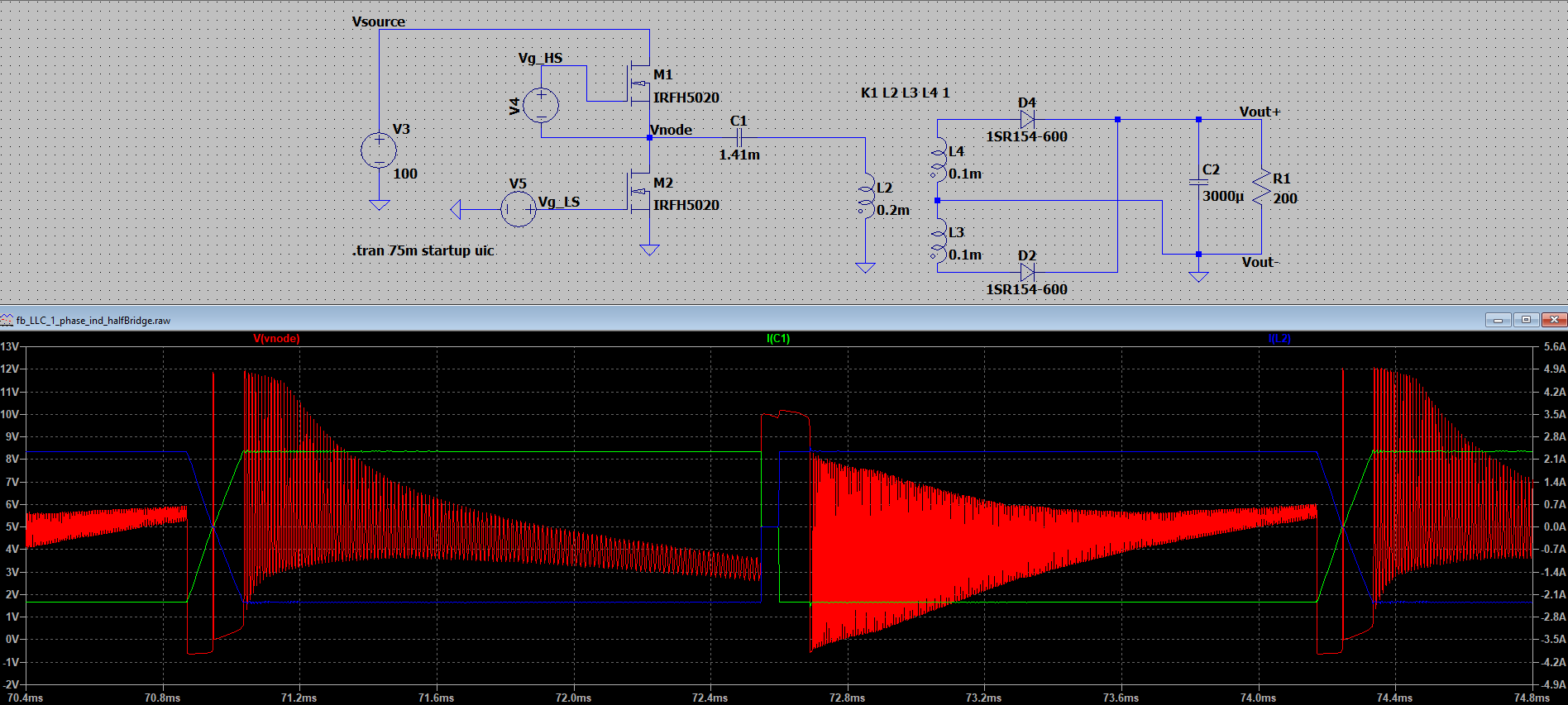
I simulated a LC-converter with a verly low static switching frequency of 300 Hz. I expected the current in C1 and L2 in a sinosoidal shape but instead it is almost a square wave. Also there is a oscillation on the voltage Vnode of 75 kHz.

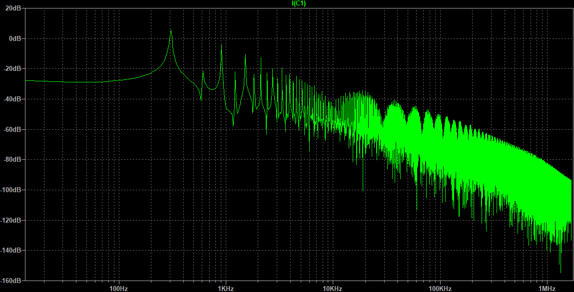
In the FFT of I(C1) it can be seen that the fundamental frequency is at the resonant frequency of C1/L2 of 300 Hz.

Like in LC or LLC converters I expected a sinosoidal current shape. Is my expectation wrong or did I do something wrong with the simulation?

LTspice circuit

FFt of I(C1)

LTspice Netlist:

C1 N002 Vnode 1.41m
D2 N003 Vout+ 1SR154-600
D4 N001 Vout+ 1SR154-600
C2 Vout+ 0 3000µ
R1 Vout+ 0 200
L2 N002 0 0.2m
L3 0 N003 0.1m
L4 N001 0 0.1m
V3 Vsource 0 100
V4 Vg_HS Vnode PWL REPEAT FOREVER (0 5 0.00157 5 0.0016 0 0.00327 0 0.0033 5) ENDREPEAT
V5 Vg_LS 0 PWL REPEAT FOREVER (0 0 0.00163 0 0.00165 5 0.003247 5 0.00325 0 0.0033 0) ENDREPEAT
M1 Vsource Vg_HS Vnode Vnode IRFH5020
M2 Vnode Vg_LS 0 0 IRFH5020
.model D D
.lib C:\Users\hamsn\Documents\LTspiceXVII\lib\cmp\standard.dio
.model NMOS NMOS
.model PMOS PMOS
.lib C:\Users\hamsn\Documents\LTspiceXVII\lib\cmp\standard.mos
.tran 75m startup uic
K1 L2 L3 L4 1
.backanno
.end
\$\endgroup\$
0

1 Answer 1

4
\$\begingroup\$

2 bad errors.

  1. Your transformer has far too low primary coil inductance. The primary current grows with an incredible rate to the max which the mosfet allows with the given Vgs drive. That happens even with nothing connected to the secondary and that's what you see.

  2. You charge (or actually try to charge) the output capacitor C2 with no series inductor. It's a short circuit which would in practice easily blow the fets or the rectifier or both at the startup (assuming the transformer was functional). Simulated parts generally do not burn, so you do not smell anything when you run the simulation.

My suggestion: Learn the design principles of forward DC to DC converters and restart from the beginning. Now you are drifting totally offroad.

\$\endgroup\$
1
  • 1
    \$\begingroup\$ I would suggest something in the order of 5mH for L1. The load at Vnode will only look like a series LC circuit when the rectifiers are not conducting. \$\endgroup\$ Commented May 15, 2023 at 21:22

Your Answer

By clicking “Post Your Answer”, you agree to our terms of service and acknowledge you have read our privacy policy.

Not the answer you're looking for? Browse other questions tagged or ask your own question.