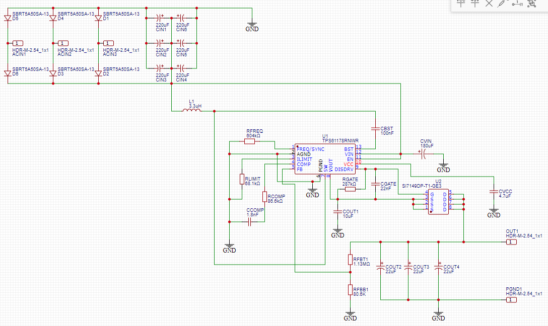
I've made a USB-C power supply that's powered by a wind turbine. It contains a boost converter and a separate buck converter.
I'm aware that there are several buck/boost USB-C power supplies out there, but none of them operate down to a low enough voltage for my liking (3 V preferred). Because of this, I elected to make my own that involves a TPS61178 boost converter which operates down to 2.7 V. The boost converter output directly powers the USB-C buck converter, which can accept voltages up to 35 V.
My current issue is that the maximum input voltage for the buck converter is 20 V. So, on a windy day, if the turbine output voltage exceeds 20 V, I want to be able to bypass the boost converter completely, and power the buck converter directly from the wind turbine.
I've also noticed that the boost converter operates more efficiently when it's configured for smaller input voltage ranges, such as 3-12 V for example, instead of 3-20 V. There's overall less heat loss when the window is smaller.
Because of this, I want to take advantage of operating the boost converter with a smaller input window, but will need to design some sort of bypass for when the input voltage rises outside of the window.
Here's my main question: What components would I need to correctly make a bypass circuit? I figured a Zener diode would be involved at the very least.
The TPS61178 also has an enable pin, which I suppose I could switch-off with a transistor when the input voltage exceeds the Zener voltage.
I've included a diagram of the boost converter below. The OUT1 and PGND1 pins power the boost converter directly (not included). The wind turbine outputs 3-phase AC, so that's why the boost converter has a bridge rectifier at its input.
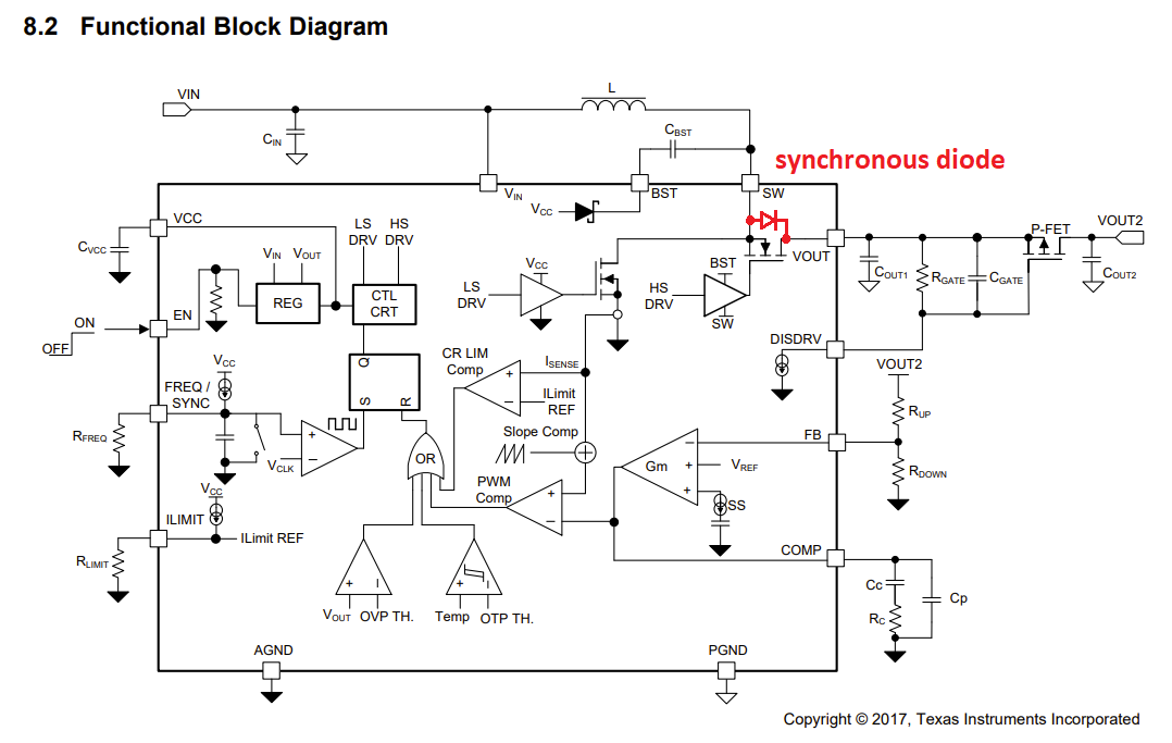
Also, here is a link to the TPS61178 datasheet: https://www.ti.com/lit/gpn/tps61178
One final thought: It dawned on me that the TPS61178 might be able to safely bypass in its current state already, but I can't tell. If that were the case, then am I over-thinking this whole thing? The datasheet mentions over-voltage protection on page 15, but it's not very detailed regarding input voltages.
Any help is appreciated, thank you!


