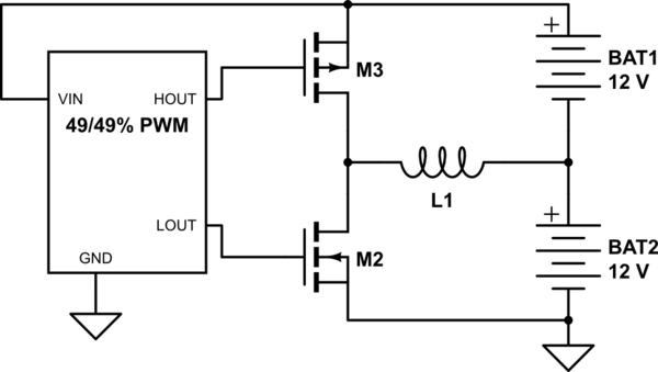
Since I currently use a 24V battery system for my house using 16 12V car batteries (2 parallel banks of 8 in series with each other) and use the lower 12V side for additional devices, (as well as due to the difference in age between batteries and occasional removal of one) there is an imbalance when charging and discharging the batteries.
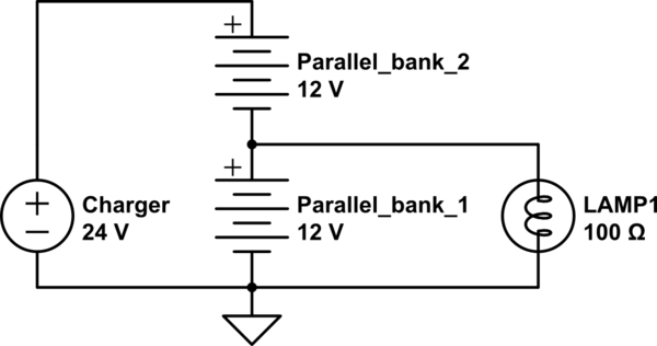
simulate this circuit – Schematic created using CircuitLab
My requirements are to have a simple circuit made with easily available materials offering up to 1A balancing current and drawing as little as possible of the quiescent current.
After a lot of drawing and brainstorming to come up with the simplest solution that works, trying to use as few transistors as possible (at the expense of having a slower and less efficient circuit) I have eventually realized it can't get simpler due to the scale of voltages involved and balances and protections needed.
So, I have resorted to the classic complementary pair MOSFET driver solution controlled by a TL494 (or KA7500) IC and came up with the schematic below:
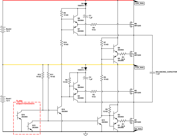
All that I need is for the capacitor to be switched about 1000 times per second between upper and lower parallel bank, which would automatically, without any measurements and logic, keep them at equal voltages.
This is accomplished by switching M1 and M3, and then M2 and M4 MOSFETS at the same time.
A simpler circuit could be made but it would be less efficient:
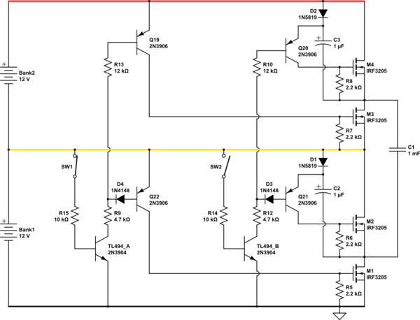
This circuit requires fewer transistors but it has somewhat poorer performance. I haven't done detailed calculations, just rough estimates which should be enough for my needs here.
Both of these circuits took a few days and many "rewirings" or rearrangements as some details are not apparent until a first schematic is drafted and looked over carefully a few times, finding an issue until all potential problems are addressed.
If anyone has better, simpler, more efficient idea or sees a problem with my circuits, feel free to suggest improvements.
I don't know if there is a more efficient IC (significantly lower quiescent current than the TL494), so those suggestions are welcome as well.
In fact, any suggestion, even including a complete IC solution, is welcome, though discrete solutions are preferred.
A simple discrete flip-flop (like an astable multivibrator typically made with 2 transistors) which includes a pause (dead-time) between opposing pulses would be great too.
EDIT: The way my circuit works is by merely switching M1 and M3 on at the same time to connect the capacitor across the lower 12V bank. Then they are turned off and M2 and M4 are turned on at the same time to connect the capacitor to the upper 12V bank. Then the cycle repeats 1000 times per second, transferring energy from the bank with higher voltage to the bank with lower voltage automatically. Basically, it's a switched capacitor design. There is a "dead time" between the ON times for the 2 pairs of MOSFETs, and they are all OFF when there are no output pulses from the TL494 IC.
EDIT 2: The batteries are charged by solar panels. The intent of this circuit is to experiment with simple battery/cell balancing circuits and principles in order to later upscale it to more batteries or cells. Also, to share a simple, workable schematic with the rest of the world.
HINT: If you want to suggest a modification to my schematics, the easiest way to do it is by opening my schematic, selecting all of its elements (Ctrl+A), copying them (Ctrl+C) and pasting them (Ctl+V) into your schematic editor in your answer. That way you don't have to redraw anything from the scratch.

