4
\$\begingroup\$

I've read a number of other similar questions to mine, but none of the answers have helped me so far. I also don't have any electrical schematic software, so I'm afraid I'll have to explain in words and picture the situation.

What I am trying to create is a basic 5v regulator that will be used to power TTL chips and LED's. In front of the 7805 is a 220uF capacitor, and another one after it. The load at the output is a 330ohm 1/2 watt resistor with an led. The middle pin is correcting connecting to the - lead. I'm trying to create:

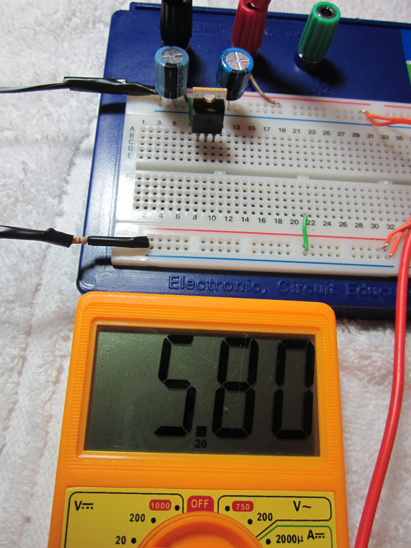
5v regulator schematic

5v regulator setup

The brown wires are connecting to my multimeter leads.
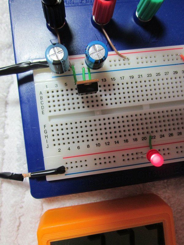
5v regulator set up

Without load, when a 9v battery is used, the regulator's output is correct at 5.00 on the dot. When I use a 7.5v 250mA DC adapter, the output is 5.8. Why is this? I've read on one forum that greater than 9 volts should be used, but another forum said that ~7v and above is fine for a 7805. I have tested another 7805 chip, with the same results.
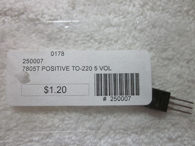
7805

My second question is about TTL chips. Earlier, I was using the 9v battery to power a 7400 quad 2-input NAND chip, and I noticed that it was functioning inconsistently. From what I read, when there are no inputs, the TTL chips will "float" and assume that all the inputs are 1. If that is the case, why are my all of my gate outputs 1 as well? If the input 1/2 are assumed to be 1, and the chip contains 4 NAND gates, shouldn't all 4 outputs be 0? The chip is functioning how I would expect an AND gate to.

Accepting the behavior of my NAND gates, I still have another confusing issue. When I do add power to one of the input pins, the output of the NAND gate will correctly become 0. However, when I remove that added power to the input pin, the output doesn't turn back back to 1! I have to the input pin with my multimeter to get it back on. Why is this? I've tested another 7400 chip, same problem.

If TTL chips need a consistent supply of ~5v, does that mean I cannot use LEDs at all? When I add a standard T-1 3/4 led to my load, the voltage drops to ~2.3, which is inadequate for my TTL chips. But a number of guides I've read online suggest experimenting with the output of TTL chips with LEDs, so I am wondering if there is a problem with my setup. The voltage drop of ~2.7 should be expected when using an LED, right?
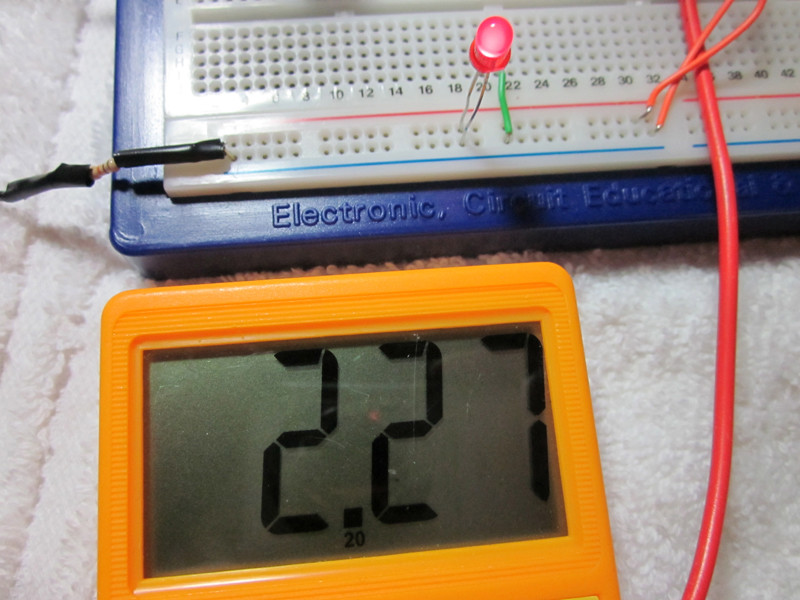
LED voltage drop

\$\endgroup\$
2
  • 1
    \$\begingroup\$ When you mention a 7.5v 250mA AC adapter are you sure the output is DC and not AC? Also if you wanted to draw a schematic there's an on-site schematic capture you can start by pressing Ctrl-M without installing any software. \$\endgroup\$
    – PeterJ
    Commented Apr 25, 2013 at 4:59
  • \$\begingroup\$ Oops, good catch. Definitely a 120v AC => 7.5v DC adapter. Also, thanks for the heads up about the on schematic tool. \$\endgroup\$
    – user22979
    Commented Apr 25, 2013 at 5:01

3 Answers 3

9
\$\begingroup\$

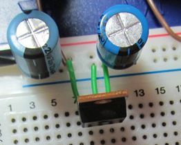
Do you know that the horizontal strips of a breadboard are all connected together (except sometimes in the middle)? To me this looks like you have shorted the input to the output of the 7805. (Or maybe the output to te ground, my view is blocked by the capacitor.)

enter image description here

====================================

OK, next step. You are using a plain old 7400, no LS or HC or any other letters between the 74 and 00? That old chip requires 5V. If you used it at 9V you can't assume it is still working correct. It might, but don't count on it.

====================================

I can't make sense of your LED question. You don't mention a series resistor, did you use one?A LED nearly always requires a series resistor. For starters, take 1k.

\$\endgroup\$
3
  • \$\begingroup\$ Yeah, sorry, not a very good picture. The input and output of the 7805 are connected to the red strip, where my positive lead comes into. Only the middle connector, the ground, is going to the blue strip. So I don't think it is being shorted. \$\endgroup\$
    – user22979
    Commented Apr 25, 2013 at 5:41
  • 2
    \$\begingroup\$ "The input and output of the 7805 are connected to the red strip" - hence they are shorted. \$\endgroup\$ Commented Apr 25, 2013 at 6:47
  • \$\begingroup\$ Holy moley, you are right! I added only the output of the regulator to the red strip, and walla! Consistent ~5v! I was thinking of something totally different when you mentioned shorting. Thanks! Going to keep this question open for the TTL and LED questions though. Probably should have made two separate threads \$\endgroup\$
    – user22979
    Commented Apr 25, 2013 at 7:08
1
\$\begingroup\$

You really want >8V or so so that the 7805 isn't dropping out, especially if there is a lot of ripple on the input (drop out is relative to the lowest part of the input).

Try it with 9-12V DC, load the output (resistor and LED is fine), and measure again.

7400 / 74LS/S/L/F/ALS etc (the true TTL models) are 5V only. 9V need not apply. CMOS based 74x is usually 2-6V supply. None are safe at 9V, AFAIK.

TTL inputs tend to float up, but it's not always a sure thing. tie them the way you want them to be certain.

Have LED's on the output through a resistor, so as to not excessively load the output, and so the LED doesn't clamp the output to Vf.

Or are you talking about LED across the supply? have it in series with a resistor. Get rid of your in line protection resistors (330ohm? I didn't quite understand, but it looks like that's what you are doing in the LED picture? they are in series with the 7805 in and out? That won't work very well if you pull any current at all...)

\$\endgroup\$
4
  • \$\begingroup\$ Hi, thanks for the reply! Sorry, I meant 2x 220uF capacitors before and after the 7805. I do have 1x 330 ohm 1/2 watt resistor in the circuit. I'm operating at an abstract level and have minimal understand of each individual part (I am currently reading a book to remedy this). As a result I keep getting parts mixed up! So you think a higher volt DC adapter will help me out? I was hesitant to buy one, but if that will solve things, it is definitely worth it. \$\endgroup\$
    – user22979
    Commented Apr 25, 2013 at 5:16
  • \$\begingroup\$ I'd look around the house first, almost certainly you'll have a wall-wart in the 9-12V range. Where in the circuit is the resistor? \$\endgroup\$
    – Marko
    Commented Apr 25, 2013 at 5:40
  • \$\begingroup\$ I might have some, but none that I'd be willing to chop the connector off of. The resistor is soldered to the negative lead of the adapter. \$\endgroup\$
    – user22979
    Commented Apr 25, 2013 at 5:43
  • \$\begingroup\$ I would guess that a lot those on this site are like me, who may throw away a non-functional piece of electronics gear, but always saves the wall-wart, much to my spouse's disapproval. I have a whole box of them, just waiting for a future project. \$\endgroup\$
    – tcrosley
    Commented Apr 25, 2013 at 20:35
0
\$\begingroup\$

Whatever other problems you may have, you need some smaller capacitors with drastically lower series resistance across the regulator output (and preferably input as well) to stabilize it.

The large electrolytics you have provided do part of the job - smoothing lower frequency variations - but they cannot respond quickly enough to counter high frequency issues.

Many regulators will output the wrong voltage without these capacitors. Also, digital multimeters may respond erroneously to signals with high frequency noise present.

\$\endgroup\$

Your Answer

By clicking “Post Your Answer”, you agree to our terms of service and acknowledge you have read our privacy policy.

Not the answer you're looking for? Browse other questions tagged or ask your own question.