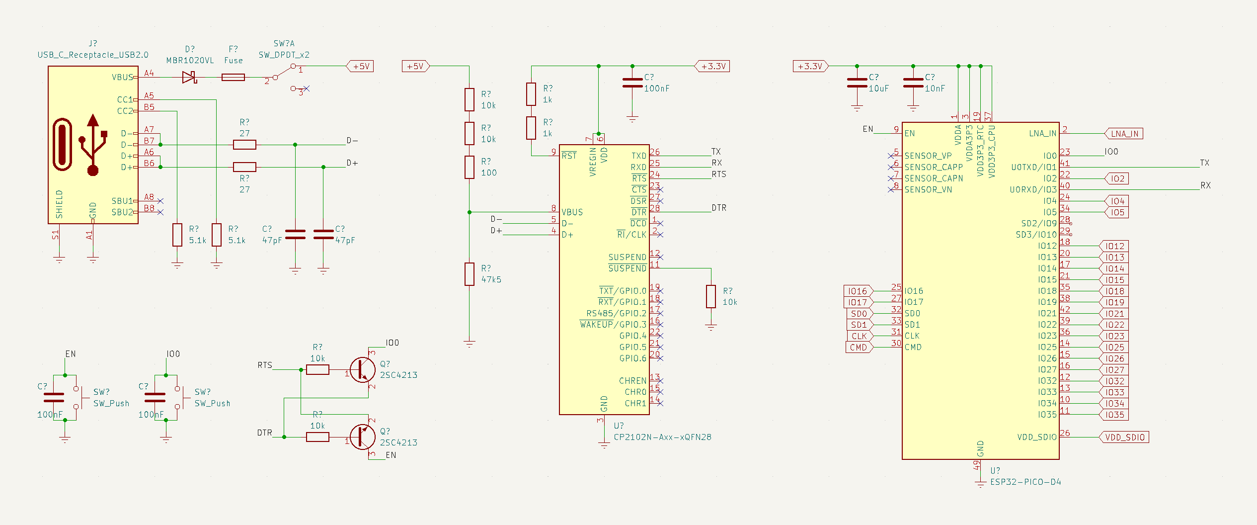
 Context: I designed some PCBs for a device that uses the ESP32-PICO-D4 as a backbone connected with USB-C via the CP2102N. I manually assembled my PCB incrementally as to detect problems immediately as they come. Unfortunately, I did not get very far. I have only assembled the ESP32 section of the PCB and I cannot flash any code to the chip.
Problem: I am unable to flash any code to the ESP32 chip, As far as I can tell, my schematic seems to be correct and in-line with existing devices. When trying to upload any code, the Arduino IDE gives me the No serial data received error.
I used both this and this schematic as reference, as well as the datasheets of each chip. I don't see how it can be a design issue (provided I'm not missing something)?
A schematic review would help point me in the right direction before I turn my troubleshooting aim to the PCB itself or any other "physical" type issues. A second pair of eyes or opinion would very much be appreciated.
Suspects and Additional Details:
Under the assumption the schematic is correct, I suspect the following:
- The problem appears to be on the ESP32 side, not necessarily with the CP2102. I don't know how many people here are familiar with Rust, but I am using the espflash flash tool to load my Rust code onto the chip. Espflash detects the presence of a CP2102 serial device (so does the Arduino IDE) they just both have problems actually connecting to the ESP32. This for sure indicates some problem with the loading of code onto the ESP32 chip and/or with the RX/TX lines. I test with both the Arduino IDE and espflash.
- I suspect that the problem might have to do with the PCB itself, however (both before manufacturing and after) I made sure to check the routing, DRC, etc. multiple times. When researching about the nature of the error, it does unfortunately give evidence to this suspicion. The No serial data received error occurs when there is an issue with the RX/TX lines are not working or the ESP32 can't reset into download mode. I did not see any problems with the PCB visually.
- Improper soldering or some sort of short? This is not the most likely but still something I considered. I verified all solder connections, everything looks good and both the CP2102 and ESP32 are soldered cleanly.
- All voltage levels are where they should be; the USB-C is spitting out ~4.9V (post schottky diode) and the linear regulator is giving me ~3.28V.
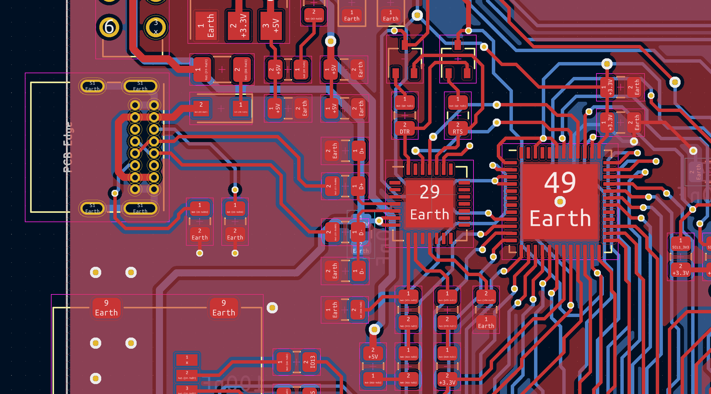
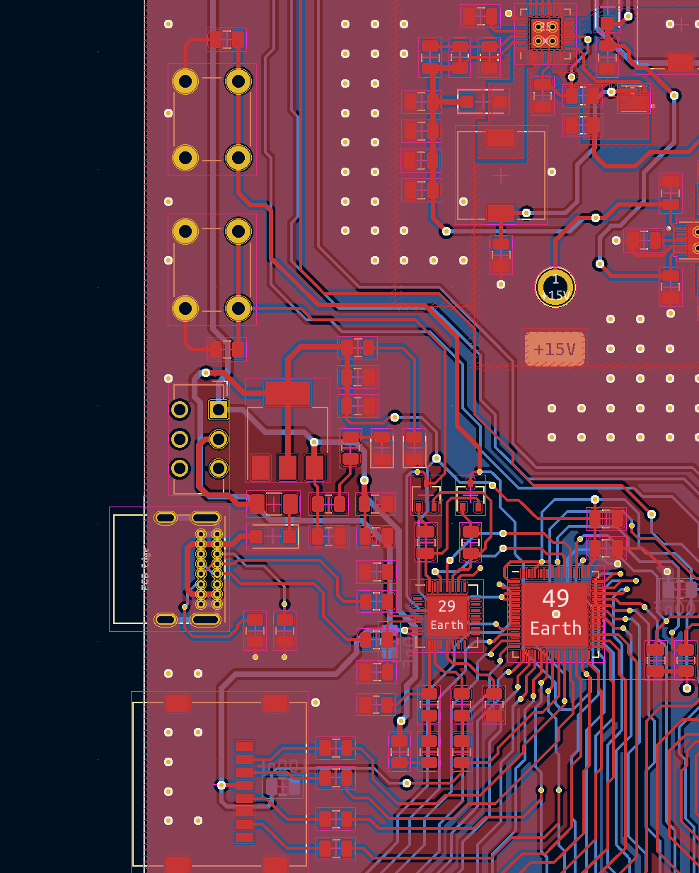
I'm not sure how much help this will be, but here is the layout for the ESP32 section of my PCB:

This is a four layer board; I removed the two middle layers (GND planes) for better visibility.
Any additional critiques of both the schematic and layout are encouraged!

