0
\$\begingroup\$

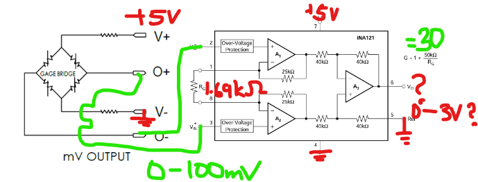
I am applying a high load (150-200lbf) to a (mV Wheatstone bridge) load cell rated for 200lbf (link to datasheets at bottom), and amplifying the differential signal with the INA121 instrumentation amplifier. I am using a pretty basic circuit, with a gain of ~30 (1.69kOhm gain resistor), and the amplifier and load cell are both powered by 5V/GND power from an Arduino.

Circuit diagram

The circuit works as expected, linearly amplifying the load cell signal, up until the output voltage approaches ~2.3V (corresponding to 75mV differential voltage, or ~150lbf).

After reaching this point, when I increase the load, I can measure the differential voltage increasing at the input terminals of the amplifier. However, the output signal changes minimally, reaching a maximum of around 2.5V, even though I have tested the amplifier to be able to reach up to 4V just connecting the inputs to high and ground.

I can't seem to figure out what is wrong with the circuit, it's especially weird to me that I can measure that the load cell is outputting the correct differential signal at the amplifier pins, but it just isn't being amplified correctly even though the amplified signal is nowhere near the maximum output of the amplifier. I could be misunderstanding something, any help would be greatly appreciated!

Load Cell: https://www.te.com/commerce/DocumentDelivery/DDEController?Action=showdoc&DocId=Data+Sheet%7FFX29%7FA5%7Fpdf%7FEnglish%7FENG_DS_FX29_A5.pdf%7F20009605-55

Amplifier: https://www.ti.com/lit/ds/symlink/ina121.pdf?HQS=dis-dk-null-digikeymode-dsf-pf-null-wwe&ts=1683396445256&ref_url=https%253A%252F%252Fwww.ti.com%252Fgeneral%252Fdocs%252Fsuppproductinfo.tsp%253FdistId%253D10%2526gotoUrl%253Dhttps%253A%252F%252Fwww.ti.com%252Flit%252Fgpn%252Fina121

\$\endgroup\$

2 Answers 2

2
\$\begingroup\$

Your power supply rails on the instrumentation amplifier are too low.

With >75mV of differential voltage, the internal voltages at the input amplifier output nodes are too close to the supply rails.

See the graphs at then bottom of page 4 of the amplifier datasheet. Your situation is similar to +/- 2.5V.


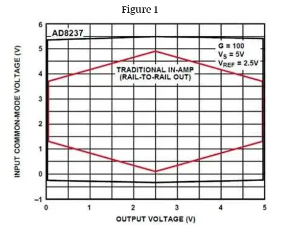
To better predict (internal and external) saturation characteristics, have a look at Analog Devices' Diamond Plot tool (so called because the typical saturation characteristics of an instrumentation amplifier are represented by the area outside a diamond shape).

Some inamp topologies use current summing so they avoid some of the more irritating characteristics of the classic 3-amplifier instrumentation amplifier.

See, for example, this comparison:

enter image description here

Even though the inamp is 'rail-to-rail output', that does not mean that any combination of input common mode voltage and output voltage is within the operating range.

\$\endgroup\$
4
  • \$\begingroup\$ I've also tried testing the circuit with 3.3V supplied to the load cell (so a range of 0-66mV input voltage), but get the same issue with the op amp operating linearly up until a certain point well below the max output voltage, where it seems to stop increasing significantly (around 1V). Would what you described still be applying in this situation? \$\endgroup\$
    – Eric
    Commented Jun 2, 2023 at 23:19
  • \$\begingroup\$ Yes. It's worse with 3.3V on the load cell since the inputs are centered around 1.65V. \$\endgroup\$ Commented Jun 3, 2023 at 0:05
  • \$\begingroup\$ Thanks for your help, I didn't know anything about the diamond plot until now. What's the reason my situation is more similar to the +/-2.5V chart rather than say the +/-5V chart if I'm supplying the in-amp with >5V? I edited a diagram in my original post to show what I think is the operating range of the amplifier (highlighted in yellow) and the common mode range assuming I'm supplying 5V to the load cell (red line). It seems like it would be in the operating range, but I think I might not be understanding something correctly here. \$\endgroup\$
    – Eric
    Commented Jun 3, 2023 at 1:38
  • \$\begingroup\$ The total supply voltage is 5V in your case and your input common mode voltage is close to 0V if you consider it as +/-2.5V. That's a good thing. If your input common mode voltage was much different from the middle of the supply rails your results would be even worse. \$\endgroup\$ Commented Jun 3, 2023 at 1:48
0
\$\begingroup\$

You may need a negative supply. Connecting the reference pin to V- (ground in your schematic) may cause issues. Plus, the input common mode range is pretty tight as shown in the data sheet on page 4 and it looks like you are just falling out of range since the common mode voltage is happiest 0.5 V above the midpoint.

There are more modern IAs that may work better for your application.

\$\endgroup\$
2
  • \$\begingroup\$ Oh interesting, I'll have to look into understanding the input common mode range charts. I don't have access to a negative supply right now, would you happen to know any common modern IA models I could try? \$\endgroup\$
    – Eric
    Commented Jun 2, 2023 at 23:23
  • \$\begingroup\$ @Eric Analog Devices and Texas Instruments have many to choose from. Mind the common mode graphs. \$\endgroup\$
    – qrk
    Commented Jun 3, 2023 at 0:39

Your Answer

By clicking “Post Your Answer”, you agree to our terms of service and acknowledge you have read our privacy policy.

Not the answer you're looking for? Browse other questions tagged or ask your own question.