-1
\$\begingroup\$

FACT: When resistors \$R_1\$ and \$R_2\$ are connected in series, they can be replaced by an "equivalent" resistor \$R_1+R_2\$ (in the following I am using \$R\$ and subscripts to denote both the resistor and its resistance).

I am looking for a proof of this fact, but let me clarify what I know and what I am looking for.

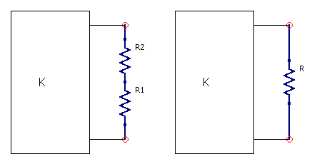
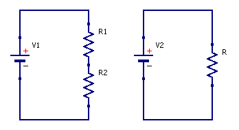
I emphasize that I know the "proofs" in which you set up two circuits as in the following picture

enter image description here

and then write the mesh equation and conclude that \$R=R_1+R_2\$. I also know that the series combination on the left has the same \$v\$-\$i\$ characteristic as the single resistor on the right.

What I am looking for is more general and refers to the next picture. enter image description here
Theorem. Let \$K\$ be any linear passive network with \$N\$ nodes and \$M\$ meshes. Call the node voltages in the left configuration \$v_n\$ and the current meshes \$i_m\$; call them \$u_n\$ and \$j_m\$ in the right configuration. Then: for each \$n\$ we will have \$v_n=u_n\$ and for each \$m\$ we will have \$i_m=j_m\$.

What I want is a proof of the above theorem (this is what I understand by the term "equivalent resistor".)

Here is a "proof-sketch" that I believe can be expanded to a full proof.

  1. In what follows \$K_1\$ is the left circuit of the second picture and \$K_2\$ is the right circuit.
  2. Write the matrix equations for mesh currents of \$K_1\$.
  3. Take any mesh which contains either of \$R_1\$ and \$R_2\$; since they are in series, either both are contained in the mesh or neither. Call the mesh current \$i_k\$.
  4. Any matrix coefficient multiplying \$i_k\$ will contain the sum \$R_1+R_2\$, since both resistors are contained in the mesh.
  5. Now write the matrix equations for mesh currents of \$K_2\$. The meshes of \$K_1\$ and \$K_2\$ are exactly the same, except that wherever \$R_1\$ and \$R_2\$ appear in \$K_1\$, \$R\$ appears in \$K_2\$. Also the sources appearing in a mesh of \$K_1\$ will be exactly the ones appearing in the corresponding mesh of \$K_2\$.
  6. In the \$K_2\$ equations replace the resistance \$R\$ with \$R_1+R_2\$. Now the equations for \$K_1\$ and \$K_2\$ are exactly the same and hence have exactly the same solution (same mesh currents).
  7. From equality of mesh currents follows equality of node voltages.
  8. Hence the two circuits are equivalent in the sense that all mesh currents and node voltages are the same. QED

Is the above correct? Is it overkill? Is there a simpler way? Any help will be greatly appreciated.

PS1: By a similar argument, using node voltage (rather than mesh current) equations we can prove the formula for parallel resistors.

PS2: I have looked for some proof of the above in many many circuit books, both introductory and advanced, and could not find it. I also searched similar topics in Stack Exchange; the closest I got was the following two

Defintion of equivalent circuit

Equivalent circuit and substitution

The answers proposed (as best as I understand them) were responding along the lines of connecting a single voltage source to the series resistors and the "equivalent" resistor and showing that voltage and current are the same in both cases. I repeat that I do understand this argument; what I am asking is a proof for the case in which an entire circuit is connected. I should add that the asker got little sympathy in the above referenced questions but, in my opinion, his original question and requests for clarification were entirely valid.

\$\endgroup\$
4
  • 7
    \$\begingroup\$ It seems like you are trying to prove that 1 + 1 = 2 \$\endgroup\$
    – Andy aka
    Commented Jun 11, 2023 at 16:06
  • \$\begingroup\$ KVL applies whether the resistors are connected to a voltage source or to a complex circuit. \$\endgroup\$
    – The Photon
    Commented Jun 11, 2023 at 16:44
  • \$\begingroup\$ The answer by Andy Aka is not helpful at all. Regarding answer by The Photon, I do not see any mention of what is happening inside K, which what I was asking for in the first place. \$\endgroup\$
    – kehagiat
    Commented Jun 11, 2023 at 17:19
  • 1
    \$\begingroup\$ @kehagiat See Advanced Series In Electrical and Computer Engineering -- Vol 5. Within it, find Graph Theory and It's Engineering Applications by Wai-Kai Chen, 1997. Be familiar with directed graphs, matrix concepts, their four spaces, columnspace, rowspace, and their corresponding left and right nullspaces, how both KVL (mesh) and KCL (nodal) occupy these spaces, and how to apply the rank-nullity theorem therein (it's slightly subtle.) In short, don't ask applied electronics engineers but rather ask applied mathematicians when you want proofs. \$\endgroup\$ Commented Jun 11, 2023 at 20:18

6 Answers 6

5
\$\begingroup\$

Is the above correct?

Yes

Is it overkill?

Yes

Is there a simpler way?

Yes. However, you don't seem to want to accept that you have already found it. You wrote

I also know that the series combination on the left has the same v-i characteristic as the single resistor on the right.

That is the simpler way. It is true for all K, as K is irrelevant. What happens inside K is independent of how the total resistance between its two terminals is implemented.

\$\endgroup\$
3
\$\begingroup\$

The proof sketch seems to both be a bit overcomplicated (possibly circular in regard to point 3) and also set unnecessary conditions (i.e. that K be linear and passive).

Looking at the same system from the point of view of nodal analysis, without the restriction that K be linear and passive:

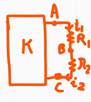
enter image description here

The only requirement I will impose is that no element of K is a dependent source whose controlling quantity involves the voltage at node B.

Suppose that we attempt to solve the overall circuit through nodal analysis. The following proof sketch should show equivalence. Note that most of this proof is just pre-work to separate the series resistors from the rest of the circuit; the actual series combination is the one simple algebraic rearrangement that I'm confident you've seen countless times.

  • By KCL at node B, i1 = i2. Without loss of generality, let's use i1 to refer to the directed current that's marked by both i1 and i2 in the figure.
  • After writing KCL at node A (of the form [unknown currents] + i1 = 0) and substituting branch constituent equations, we will get an equation of the form [unknown branch constitutive terms] + (Va - Vb)/R1 = 0
  • We do the same thing at node B, and obtain [unknown branch constitutive terms] + (Vb - Vc)/R2 = 0.
  • Note that the only equations mentioning node B are the ones listed explicitly here. The other unknown branch constitutive terms are internal to K and cannot mention the voltage at node B.
    • To make it clear - Nothing happens inside K. Any branches internal to K are listed under [unknown branch constitutive terms] - With the exception of our one condition that node B does not participate in branch constitutive relations inside K, we will neither manipulate these terms nor require any properties from them from this point onward.
  • So far, all we've done is set up and isolate the series branch.
  • In order to reduce the composite circuit of R1 and R2, we want to find a branch constitutive equation that relates the current i1 to the voltage drop Va - Vc.
  • We know that \$ (V_a - V_b) / R_1 = i_1 \$ and likewise \$ (V_b - V_c) / R_2 = i_1\$. We rearrange the first as \$V_a - V_b = i_1 R_1\$, the second as \$V_b - V_c = i_1 R_2\$, and add corresponding sides of both equations to get \$V_a - V_c = i_1 (R_1 + R_2)\$.
  • Dividing both sides by \$R_1 + R_2\$ yields us a branch constitutive equation \$i_1 = (V_a - V_c) / (R_1 + R_2)\$, which can be interpreted topologically as:
    • A single component connected across V_a and V_c
    • With the same exact branch constitutive equation as a resistor with value R_1 + R_2
    • And no internal node that is relevant to any other equations in the circuit.
    • And is hence indistinguishable from a single resistor with value R1 + R2.

No matter what is happening inside K (linear, nonlinear, passive, active, stable, oscillatory, chaotic, etc) the only way K observes R1 and R2 is through the voltages and and currents at A and C. Nothing about K changes when we do this simplification. It will maintain the same voltages, currents, and dynamics. This should come as no surprise - we have refactored the subcircuit consisting of R1 and R2 while maintaining the same voltages, currents, and relation between them as K can observe through A and C.

All equations internal to K are unchanged, the equations at the boundary are unchanged, and hence the internal voltages/currents of K in any solution to those equations are unchanged.

\$\endgroup\$
10
  • \$\begingroup\$ Nanofarad, I find your answer much more helpful than all the previous ones. You obviously took the trouble to respond in detail and I am quite sure I follow your reasoning. Still, I do not see where you address what is happening INSIDE the circuit K, which was my original question and the thrust of my theorem (conjecture really). If you are interested in continuing this, perhaps we should start by defining "equivalent resistance". Also, because I do not want to tire innocent observers, is there some mechanism to continue this discussion off the forum? \$\endgroup\$
    – kehagiat
    Commented Jun 11, 2023 at 17:23
  • 2
    \$\begingroup\$ @kehagiat Why does it not answer your question? By having an answer that doesn't depend on what happens inside K, you can see that the result is true regardless of what K is. \$\endgroup\$
    – Hearth
    Commented Jun 11, 2023 at 17:27
  • 1
    \$\begingroup\$ @kehagiat Nothing happens inside K. The whole point is that K is irrelevant under the given condition, because its branch constitutive equations do not participate in the branches being reduced. No matter what equations and dynamics govern K (passive, active, linear, nonlinear, stable, oscillatory, chaotic, etc) it doesn't matter. The only transformation needed for an equivalent resistance of series bits outside of K is that done on bits outside of K. \$\endgroup\$
    – nanofarad
    Commented Jun 11, 2023 at 17:33
  • 1
    \$\begingroup\$ @kehagiat What proof are you looking for? The only thing the resistors can possibly do to change the circuit are to change the current through them, and this answer explains that regardless of what K is, the substitution does not result in a changed current. How else do you propose the resistors would affect the rest of the circuit? \$\endgroup\$
    – Hearth
    Commented Jun 11, 2023 at 17:52
  • 1
    \$\begingroup\$ @kehagiat It's in there already - I do the work of actually simplifying the resistors to show that all equations internal to K are unchanged because they involve the same unchanged voltages, currents, and relationship among them, to elements outside K. If the equations governing K are unchanged, then the solution to those equations is unchanged as well. \$\endgroup\$
    – nanofarad
    Commented Jun 11, 2023 at 17:53
2
\$\begingroup\$

A linear relationship between voltage across a resistor to the current through a resistor is implicit in the definition of a resistor. To see this, one only need consider components with non-linear relationships between voltage and current, such as diodes.

Once we assume that each of two different components has a linear relationship between voltage and current, it follows that when these two components are connected in series (or in parallel) that their combination also has a linear relationship between current and voltage.

The value of the combined resistance then follows from Ohm's and Kirchhoff's laws. However it cannot be deduced by these laws alone, nor from Maxwell's-Heaviside's laws alone. One must assume the linear relationship between voltage and current, and that assumption does not apply to all components.

Thus, in a way, the series equivalent law for resistors is implicit in the definition of "resistors".

\$\endgroup\$
1
\$\begingroup\$

Just a Kirchhoff's laws.

  1. Single R have a functional dependence between voltage drop at ends and current through it: V = R * I

  2. Law 1. Voltage drop along some line is a sum of drops on elements of this line.

  3. Law 2. Sum of currents at some junction equal to 0

x*. Let set "resistance" of some bipolar circuit as a quotient of Voltage drop by a current at the end of this circuit

That's enough.

\$\endgroup\$
3
  • \$\begingroup\$ Theoristos, I have the same comment / question as above: how in your answer are you addressing my question, namely what is happening inside the circuit K? \$\endgroup\$
    – kehagiat
    Commented Jun 11, 2023 at 17:21
  • 1
    \$\begingroup\$ @kehagiat The circuit K is entirely irrelevant because all the resistors see is the port where they connect to \$\endgroup\$
    – Justme
    Commented Jun 11, 2023 at 17:33
  • \$\begingroup\$ @kehagiat: Same answer as Justme : linear circuit states, that one can divide the whole circuit into parts-"black boxes", behave independently inside each other and dependent each other only on limited "connections". If you need to take into account things like mutual capacitance - you need to add some additional circuit brances. \$\endgroup\$
    – Theoristos
    Commented Jun 18, 2023 at 13:56
1
\$\begingroup\$

Is the above correct?

Yes

Is it overkill?

I find it a cluttered approach that I would not use to explain.

Is there a simpler way? Any help will be greatly appreciated.

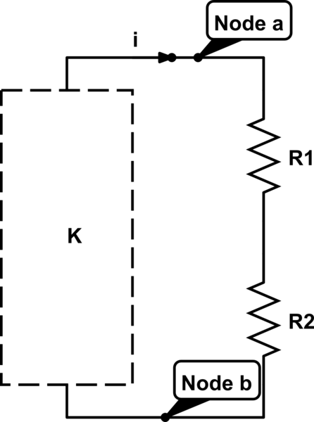
In the diagram below, the current \$i=i_k-i_{k+1}\$, the difference between the mesh currents where the branch containing \$R_1\$ and \$R_2\$ form the boundary between the two meshes. Nodes \$a\$ and \$b\$ contain the branch.

For any and every arbitrary Kirchhoff path through a complicated linear circuit K, as described by the OP, Kirchhoff's voltage law requires that the sum off all voltages across the path elements equals zero.

Therefore, $$v_{ab}=v_{R1}+v_{R2}$$ regardless of the path taken through K.

The resistance $$R=R_{ab}= \frac{v_{ab}}{i}$$

So, by conservation of charge, (elements in series must have the same current):$$R=R_{ab}= \frac{v_{R1}}{i}+\frac{v_{R2}}{i}$$

Therefore $$R=R_1+R_2$$

This is far simpler and is based on Ohm's Law and established circuit theory, without having to solve complicated matrices. I'll leave that to the mathematical folks.

schematic

simulate this circuit – Schematic created using CircuitLab

\$\endgroup\$
1
\$\begingroup\$

Taking into account all the answers and comments that appeared in the thread, I now have an answer which satisfies me (hopefully some of the other participants as well). I present my answer in the form of two theorems.

The first theorem has limited scope but I believe the proof is correct and, more importantly, gives the intuition on why \$R_{eq}\$ must equal \$R_{1}+R_{2}\$.

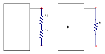
Theorem 1. Let \$K\$ be any linear resistive network without current sources and without dependent voltage sources. From \$K\$ construct the networks \$K_{1}\$ (left picture) with \$M_{1}\$ independent loops and \$K_{2}\$ (right picture) with \$M_{2}\$ independent loops of \$K_{2}\$.

enter image description here

The following hold

  1. \$M_{1}=M_{2}=M\$

  2. If \$l_{1}, ..., l_{M}\$ are independent loops of \$K_{1}\$, then they are also independent loops of \$K_{2}\$ and conversely, except that: every \$K_{1}\$ loop containing the branches \$R_{1},R_{2}\$ corresponds to a \$K_{2}\$ loop containing the branch \$R\$.

  3. If \$R=R_{1}+R_{2}\$ then:

3.1 Let \$i_{1},...,i_{M}\$ be the currents of \$l_{1}\$, ..., \$l_{M}\$ in \$K_{1}\$ and \$j_{1},...,j_{M}\$ be the currents of \$l_{1}, ..., l_{M}\$ in \$K_{2}\$. Then, for \$m=1,...,M\$, we have \$i_{m}=j_{m}\$.

3.2 Let \$1,...,N\$ be the nodes of the original network \$K\$, \$v_{1},...,v_{N}\$ their voltages in \$K_{1}\$ and \$u_{1},...,u_{N}\$ their voltages in \$K_{2}\$. Then, for \$n=1,...,N\$, we have \$v_{n}=u_{n}\$.

Proof. Parts 1 and 2 are obvious.

For part 3.1 we note that \$i_{1},...,i_{M}\$ are the unique solution of \$M\$ linear equations: $$ \text{for }k=1,...,M:a_{k1}i_{1}+...+a_{kM}i_{M}=V_{k} $$ and \$j_{1},...,j_{M}\$ are the unique solution of \$M\$ linear equations: $$ \text{for }k=1,...,M:b_{k1}j_{1}+...+b_{kM}j_{M}=U_{k}% $$ For each \$k\$ we have \$V_{k}=U_{k}\$. If \$R_{1}R_{2}\$ is not part of the \$k\$-th loop then, for \$m=1,...,M\$ we have \$a_{km}=b_{km}\$. If \$R_{1}R_{2}\$ is part of the \$k\$-th loop then, for \$m\neq k\$ we have \$a_{km}=b_{km}\$ and for \$m=k\$ we have \begin{align*} a_{kk} & =R_{1}+R_{2}+(\text{all other resistances on }k\text{-th loop})\\ b_{kk} & =R+(\text{all other resistances on }k\text{-th loop})=R_{1}% +R_{2}+(\text{all other resistances on }k\text{-th loop}) \end{align*} It follows that both \$(i_{1},...,i_{M})\$ and \$(j_{1},...,j_{M})\$ are solutions of the same system of equations. Since the system has a unique solution, \$(i_{1},...,i_{M})=(j_{1},...,j_{M})\$.

For part 3.2, we note that the loop currents uniquely determine the node voltages. \$\blacksquare\$*

The second version has more general scope but the proof will be a lot messier. I just give a sketch and I am not sure I have covered all possible holes, but the general idea should be clear enough.

Theorem 2. Let \$K\$ be any network. From \$K\$ construct the networks \$K_{1}\$ (left picture) with \$M_{1}\$ independent loops and \$K_{2}\$ (right picture) with \$M_{2}\$ independent loops of \$K_{2}\$. Then all the conclusions of Theorem 1 hold, except that \$(i_1,...,i_M)\$ must be understood as some solution of \$K_1\$ and \$(j_1,...,j_M)\$ a "corresponding" solution of \$K_2\$ (and similarly for the node voltages).

Proof Sketch. The correspondence of loops in \$K_1\$ and \$K_2\$ still holds.

To determine the loop currents in \$K_1\$ we can use KVL to write equations of the form $$ \text{for } k=1,...,M: \sum_{b\in l_k} f_{b}(i_1,...,i_M)=V_k $$ where the sum is over all branches in the \$k\$-th loop and \$ f_{b}(i)\$ is the v-i characteristic of the \$b\$-th branch. Some additional equations may be required for current sources, but they will not involve the current through \$R_1R_2\$ (\$K_1\$ cannot contain sources dependent on the current through / voltages across \$R_1,R_2,R\$ because the only sources would appear in the original \$K\$, which did not contain \$R_1,R_2,R\$).

Without loss of generality, let the first branch be \$R_1\$, the second branch \$R_2\$. For each loop \$k\$ which contains these two branches we will have \$f_{1}(i_1,...,i_M)=R_1i_1\$ and \$f_{2}(i_1,...,i_M)=R_2i_1\$.

The \$K_2\$ equations are exactly the same, except that \$f_{1}(i_1,...,i_M)=Ri_1\$ (the first branch is the one which contains \$R\$, the second branch is unrelated).

Hence the equation systems of the two networks are identical and they possess the same solution sets (each network may have zero, one or more solutions). \$\blacksquare\$

Here are some concluding remarks.

  1. I understand that all the above is much ado about little. The reason I originally embarked on all this is the following. It is common practice to solve a network by first applying various simplifications of resistance combinations, then solving the simplified network and finally transferring the results to the original neywork. I have seen this done as a matter of fact in a number of textbooks and I have done it myself. But at some point I wanted to make sure that the resistance simplifications did not change anything (important) in the original network. In other words I wanted a proof and I could not find one. That's why I asked.

  2. Most of the answers and comments appearing here helped me in many ways, but especially to clarify my thinking. Special thanks to periblepsis, Neil_UK, nanofarad (especially), Hearth, Math Keeps Me Busy.

  3. Regarding the scope, i.e., how far can the basic result be extended. Of course we all know that it holds true for any (in nanofarad's sense) network. Or do we? Does it hold for networks with inductors and/or capacitors and unbounded solutions? I believe yes, but we cannot prove it by algebraic arguments. Does it hold for networks which have no solution? I believe yes, but in the sense that neither \$K_1\$ nor \$K_2\$ will have a solution. And so on

\$\endgroup\$

Not the answer you're looking for? Browse other questions tagged or ask your own question.