0
\$\begingroup\$

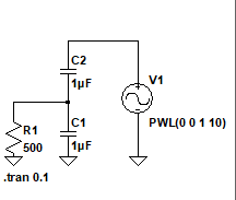
I am trying to analyse a simple circuit of series-parallel RC in LTspice .

enter image description here

V1 is a voltage source ramping from 0V to 10V in 1 second.

I am expecting to see the constant current in C2 and C1 since constant positive dV/dt is applied (10V/S) across circuit but in simulation the current in C1 goes to zero eventhough the ramping voltage is still present and current in C2 and R1 matches after some time .

enter image description here

Initially current in C1 increases along with applied dV/dt slope but reaches one point and then current discharges to zero value .

Why current in C1 ceases to zero after some time though positive dV/dt is still present ? why it can not have the constant current like C2 ? Thanks in advance.

\$\endgroup\$
0

2 Answers 2

1
\$\begingroup\$

Staying in the time domain:

$$\begin{align*} C_1\frac{\text{d}}{\text{d}t}V+C_2\frac{\text{d}}{\text{d}t}V+\frac{V}{R_1}&=C_2\frac{\text{d}}{\text{d}t}V_1 \\\\ \left(C_1+C_2\right)\frac{\text{d}}{\text{d}t}V+\frac{V}{R_1}&=C_2\cdot 10\:\frac{\text{V}}{\text{s}} \\\\ \left[\frac{\text{d}}{\text{d}t}+\frac{1}{R_1\left(C_1+C_2\right)}\right]V&=\frac{C_2}{C_1+C_2}\cdot 10\:\frac{\text{V}}{\text{s}} \\\\ \left[\frac{\text{d}}{\text{d}t}+0\right]\left[\frac{\text{d}}{\text{d}t}+\frac{1}{R_1\left(C_1+C_2\right)}\right]V&=\left[\frac{\text{d}}{\text{d}t}+0\right]\left[\frac{C_2}{C_1+C_2}\cdot 10\:\frac{\text{V}}{\text{s}}\right] \\\\ \left[\frac{\text{d}}{\text{d}t}+0\right]\left[\frac{\text{d}}{\text{d}t}+\frac{1}{R_1\left(C_1+C_2\right)}\right]V&=0 \end{align*}$$

That has the following general solution:

$$V=A_1\exp\left(\frac{-t}{R_1\left(C_1+C_2\right)}\right)+A_2$$

Initially, at \$t=0\$ then \$A_1+A_2=0\:\text{V}\$. The only remaining question is what should \$V\$ be as \$t\to\infty\$. At that time, \$V\$ won't be changing further so there will be no current in \$C_1\$. Therefore, it is valid to say that all the source's \$\frac{\text{d}\,V}{\text{d}t}\$ (which is \$10\:\frac{\text{V}}{\text{s}}\$) is applying only to \$C_2\$ and then \$I_{C_2}= 10\:\mu\text{A}\$ which has to sink into \$R_1=500\:\Omega\$. So the ending voltage is \$V=5\:\text{mV}\$ as \$t\to\infty\$.

So we can say that \$A_2= 5\:\text{mV}\$ and therefore \$A_1= -5\:\text{mV}\$ and the specific solution should be:

$$V=5\:\text{mV}\left[1-\exp\left(\frac{-t}{R_1\left(C_1+C_2\right)}\right)\right]$$

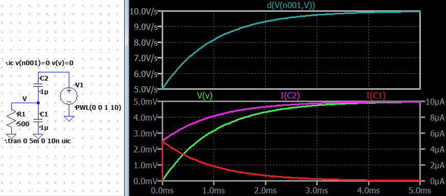
The \$\tau=R_1\left(C_1+C_2\right)=1\:\text{ms}\$. Jumping into LTspice and picking a duration of about 5 \$\tau\$ or \$5\:\text{ms}\$:

enter image description here

Which is as predicted.

I don't see any quandary.

You can now compute \$\frac{\text{d}}{\text{d}t}V\$ to estimate the currents for \$C_1\$ as \$I_{C_1}=C_1\frac{\text{d}}{\text{d}t}V\$ and for \$C_2\$ as \$I_{C_2}=C_2\frac{\text{d}}{\text{d}t}\left(V_1-V\right)=C_2\left(10\:\frac{\text{V}}{\text{s}}-\frac{\text{d}}{\text{d}t}V\right)\$. This works out to:

$$\begin{align*} I_{C_1}&=5\:\mu\text{A}\exp\left(-1000\:\text{Hz}\cdot t\right) \\\\ I_{C_2}&=10\:\mu\text{A}-5\:\mu\text{A}\exp\left(-1000\:\text{Hz}\cdot t\right) \end{align*}$$

Let's see:
enter image description here

Yeah. That looks about right.

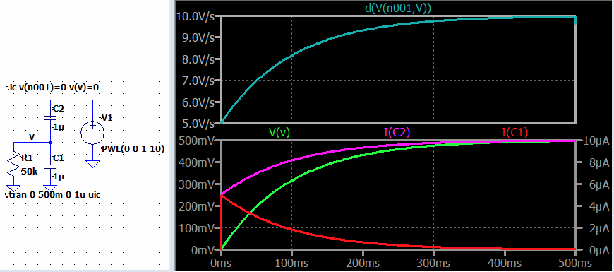
Suppose the resistor is changed to \$50\:\text{k}\Omega\$. Then \$\tau=100\:\text{ms}\$. Also, expect to see the final voltage as \$V=500\:\text{mV}\$ at \$t\to\infty\$. The current curves will look the same, except for the longer \$\tau\$ over which they stretch. So a run for \$5\tau=500\:\text{ms}\$ yields:
enter image description here

Simulation matches theory. Nice when that happens.

\$\endgroup\$
6
  • \$\begingroup\$ constant current through capacitor means its impedance is changing continuously with ramping voltage? \$\endgroup\$
    – Ronnie
    Commented Jun 21, 2023 at 16:48
  • \$\begingroup\$ @Ronnie The mathematics shows exactly what simulation shows. So theory and simulation match. Works as expected. I can't say i understand your question. But that may be my reading skills are poor. Could you rephrase your question? \$\endgroup\$ Commented Jun 21, 2023 at 19:22
  • 1
    \$\begingroup\$ @Ronnie Look at the equations I developed for the capacitor currents. You can see they are not constant. Look at the simulation for I(C1) and I(C2). Those also are not constant. At least, not at first. Once the voltage V has settled, then I(C1)=0 and then I(C2) is a non-zero constant. But not before or during the first 4 or 5 taus of time have expired. I guess this is why I'm confused by your question. It starts by saying something I've proved isn't true. \$\endgroup\$ Commented Jun 22, 2023 at 5:08
  • 1
    \$\begingroup\$ understood your point. \$\endgroup\$
    – Ronnie
    Commented Jun 22, 2023 at 5:10
  • 1
    \$\begingroup\$ @Ronnie Perhaps an issue for you to consider is that while it is true that ideal capacitors do obey the equation you mentioned, you must keep track of both sides of the capacitor for that equation to apply. Don't be blinded to what's happening on the other end, while looking at one end of it. \$\endgroup\$ Commented Jun 22, 2023 at 5:13
1
\$\begingroup\$

Maybe you are justified in thinking that current would be constant, if R1 were not there. I say maybe, because placing a voltage source directly across a capacitor produces a loop with no resistance, and strictly speaking, current in such a system is undefined, and I wouldn't trust the simulation results.

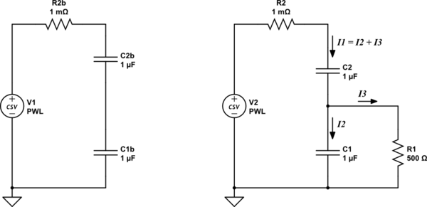
You can solve that little issue by inserting a very tiny resistance, as shown left:

schematic

simulate this circuit – Schematic created using CircuitLab

On the right, the inclusion of R1 causes a split in current between two paths. If \$I_3\$ is negligible compared to \$I_2\$ (corresponding to large R1), then obviously the behaviour you expected, constant current, won't be severely disturbed.

If \$I_3\$ is very large compared to \$I_2\$ (corresponding to small R1, and in your circuit R1 is small), then C1 is starved of current, and will hardly charge at all during the initial 1s. In that case, the voltage across C1 stays near zero, and C2 will develop almost the entire supply potential difference. Again, you would see a more-or-less constant current \$I_1\$, but twice as large, since the only capacitor being charged is C2, to almost twice the voltage.

However, there's a middle ground, a range of values of R1 for which current \$I_3\$ (through R1) becomes comparable with C1's charging current \$I_2\$. C1 is still able to charge, but as its voltage increases, so does the voltage across R1, along with current \$I_3\$. This is current stolen from C1 by R1, which severely dampens C1's charge rate. The graph of \$I_1\$ will no longer be constant or even linear.

\$\endgroup\$
2
  • \$\begingroup\$ During transient capacitor C1 current starts to rise from 0 value and once it reaches (steady state) that constant value defined by dV/dt then it stops taking current due to constant current * R1 value will always maintain constant voltage across it . is this understading correct ? Value of I3 or nature of I3 will decide the current of C1? \$\endgroup\$
    – Ronnie
    Commented Jun 20, 2023 at 12:31
  • \$\begingroup\$ @Ronnie I can't really say for sure, without a full analysis, but my intuition tells me that sounds correct. \$\endgroup\$ Commented Jun 20, 2023 at 14:05

Your Answer

By clicking “Post Your Answer”, you agree to our terms of service and acknowledge you have read our privacy policy.

Not the answer you're looking for? Browse other questions tagged or ask your own question.