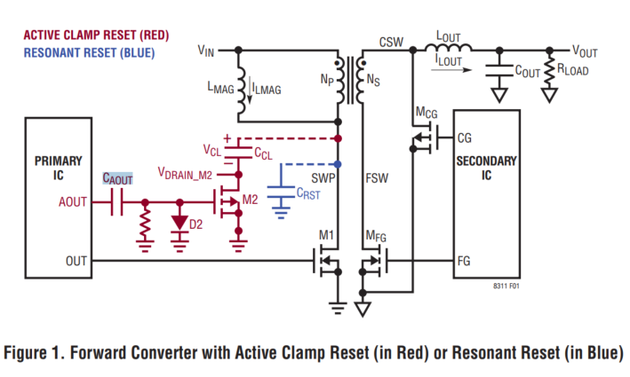
2
\$\begingroup\$

The datasheet describes CAOUT as a decoupling capacitor. Not sure how it is so ?

enter image description here

My guess on the working of the circuit:

  1. When AOUT is high, CAOUT is gradually charged with +(on left) and right terminal voltage decreasing to zero.) -Keeping M2 OFF

  2. Now when AOUT goes low, CAOUT discharges - I guess partially through R and CGS of M2. -Turning on M2. But ultimately the CAOUT charge depletes to zero because of the resistor - How do we ensure M2 remains turned ON till AOUT goes high again? Is the resistor just a weak pull down?

Is this a standard circuit to drive a P-channel low side MOSFET with source Grounded?

enter image description here

\$\endgroup\$
5
  • \$\begingroup\$ Very likely mistake..Secondary PFET would just short out the supply as drawn. Which reminds us: Have large packs of salt handy, when consuming datasheets. \$\endgroup\$
    – tobalt
    Commented Jun 26, 2023 at 7:51
  • \$\begingroup\$ It's explained more on page 30. \$\endgroup\$
    – Jon
    Commented Jun 26, 2023 at 9:17
  • \$\begingroup\$ @Jon: Sorry, could not find anything much regarding the driver Cap \$\endgroup\$ Commented Jun 26, 2023 at 10:15
  • \$\begingroup\$ The flyback is a negative voltage in respect to circuit gnd, so you need to level shift the gate drive negative. M2 only needs to be held on long enough to ‘reset’ the magnetic field so the time constant formed by caout, cgate and the pullup down (pullup??) resistor needs to be considered. \$\endgroup\$
    – Kartman
    Commented Jun 26, 2023 at 11:00
  • 2
    \$\begingroup\$ Imo, the datasheet description of Cout as "decoupling" capacitor is a typo. I would rather describe it as a "coupling" capacitor. \$\endgroup\$
    – brhans
    Commented Jun 26, 2023 at 11:14

0

Your Answer

By clicking “Post Your Answer”, you agree to our terms of service and acknowledge you have read our privacy policy.