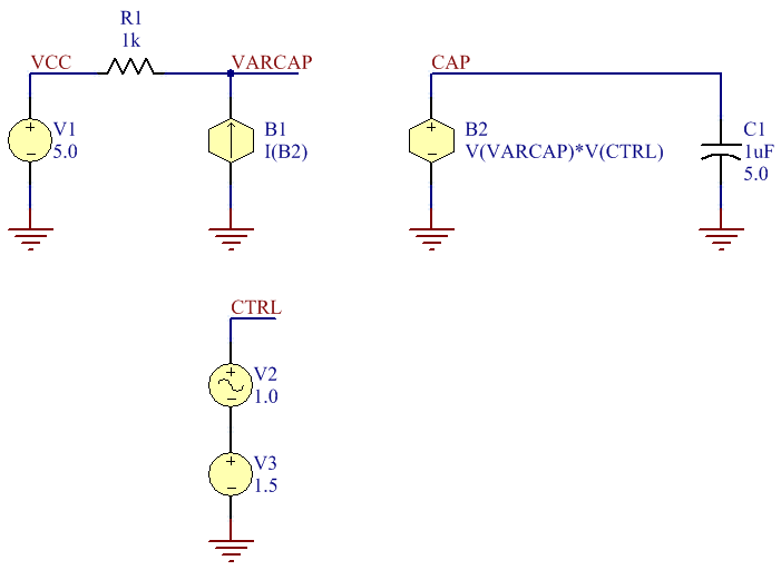
I was playing around with electret capacitors, supposedly time-varying capacitors with accordance with sound waves, trying to understand them deeply when I found that I need to model it mathematically, so I set up a really simple circuit and it's differential equation
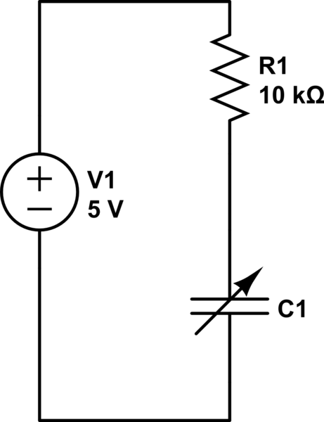
simulate this circuit – Schematic created using CircuitLab
$$ V(t) = \frac{dq(t)}{dt} R + \frac{q(t)}{C(t)} $$ And for simplicity, I set $$V(t) = 5$$ and $$C(t)= Asin(\omega t)+B ~~,~~ \text{where $B$ $>$ $A$} $$
Note: Capacitance is inversely proportional to sound waves as noted by @glen-geek, this is just a model for a capacitor that changes with time in a sinusoidal manner.
Now although I thought this would be an easy differential equation, I couldn't solve it manually with any method I could know, Bernoulli, Laplace, etc.. so I had to simulate it on a computer.
Now unfortunately again I didn't find any tool that simulates electric circuits with time varying capacitors, so I just did my own crappy simulator using python (I simply solved for dq/dt and each nudge in time I multiply it by the nudge and add it to total charge)
import math
import matplotlib.pyplot as plt
import numpy as np


def voltage(time):
    return 5


def resistance(time):
    return 10000


def capacitance(time):
    change_in_capacitance = 1e-7
    base_capacitance = 1.01e-7
    return change_in_capacitance * math.sin((100 / 2 * math.pi) * t) + base_capacitance


q = 0
t = 0
dq_dt = 0  # Should be calculated first time
dt = 10e-6

t_points = np.array([])
q_points = np.array([])
dq_dt_points = np.array([])
output_v_points = np.array([])
output_v_r_points = np.array([])


def update_dq_dt(time):
    global dq_dt, dq_dt_points, output_v_points, output_v_r_points
    dq_dt = (voltage(time) - q / capacitance(time)) / resistance(time)
    output_v_points = np.append(output_v_points, voltage(t) - dq_dt * resistance(t))
    output_v_r_points = np.append(output_v_r_points, dq_dt * resistance(t))
    dq_dt_points = np.append(dq_dt_points, dq_dt)


def update_q():
    global q, q_points
    q_points = np.append(q_points, q)
    q += dq_dt * dt


def update_t():
    global t, t_points
    t_points = np.append(t_points, t)
    t += dt


for i in range(1, 100000):
    update_dq_dt(t)
    update_q()
    update_t()

print(t_points)
print(q_points)
print(dq_dt_points)

# plt.plot(t_points, q_points, label="charge")
# plt.plot(t_points, dq_dt_points, label="current")
plt.plot(t_points, output_v_points, label="voltage output")
plt.plot(t_points, output_v_r_points, label="voltage on resistor")
plt.show()
This is supposedly a circuit simulator with resolution of 10us and as a gut check that I put capacitance a constant value, and sure enough it generated the expected exponential graph so I moved on to simulate a time varying capacitance not expecting what's going to happen next.
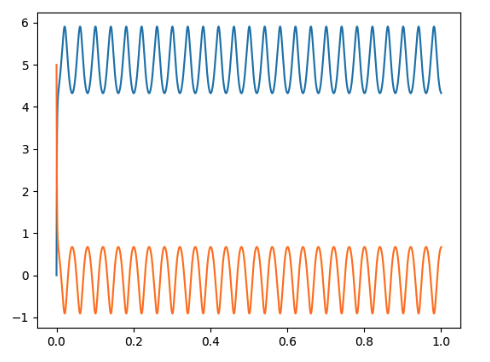
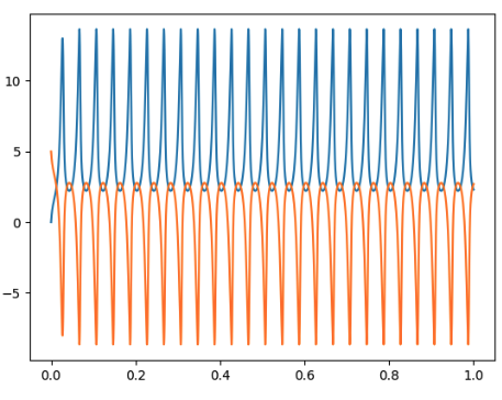
(Blue is voltage on capacitor leads, and orange is voltage on resistor)
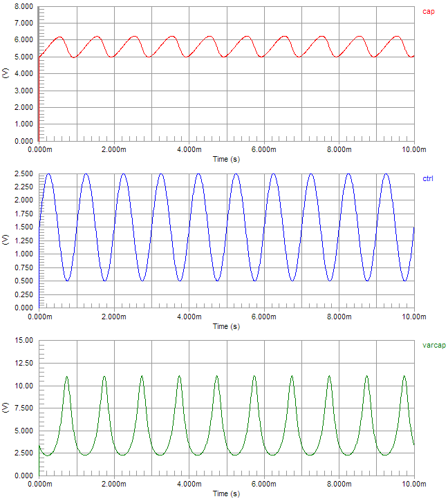
Voltage between the leads of capacitor exceeded the supply voltage (5 volts), because as capacitance changes instantaneously, sometimes charge has to move back into the source, aka current moving backwards, thus voltage on resistor is negative and as a compensation, voltage on capacitor is higher than the supply voltage.
I tried playing with the varying capacitor and could even reach double the supply voltage
Now of course practically this is I think is impossible as suggested by my practical experiment, I could barely sense any change in the voltage in the range of millivolts, actually all of this was because I was trying to find the best series resistance to put before the capacitor yet I fill into this rabbit hole.
My question in a nutshell is, Is this actually correct? and indeed the voltage on a capacitor can exceed supply voltage without the use of inductors or banks or the other regular means, and that my reasoning is correct, changing capacitance requires energy, sound waves bumping into it moving the diaphragm so indeed no laws broken here by achieving higher voltage.
And if this is actually correct, is there a possibility to construct a device that generates electricity by simply periodically igniting some fuel in such way that a piston hits hard a capacitor in the circuit to generate power?

