0
\$\begingroup\$

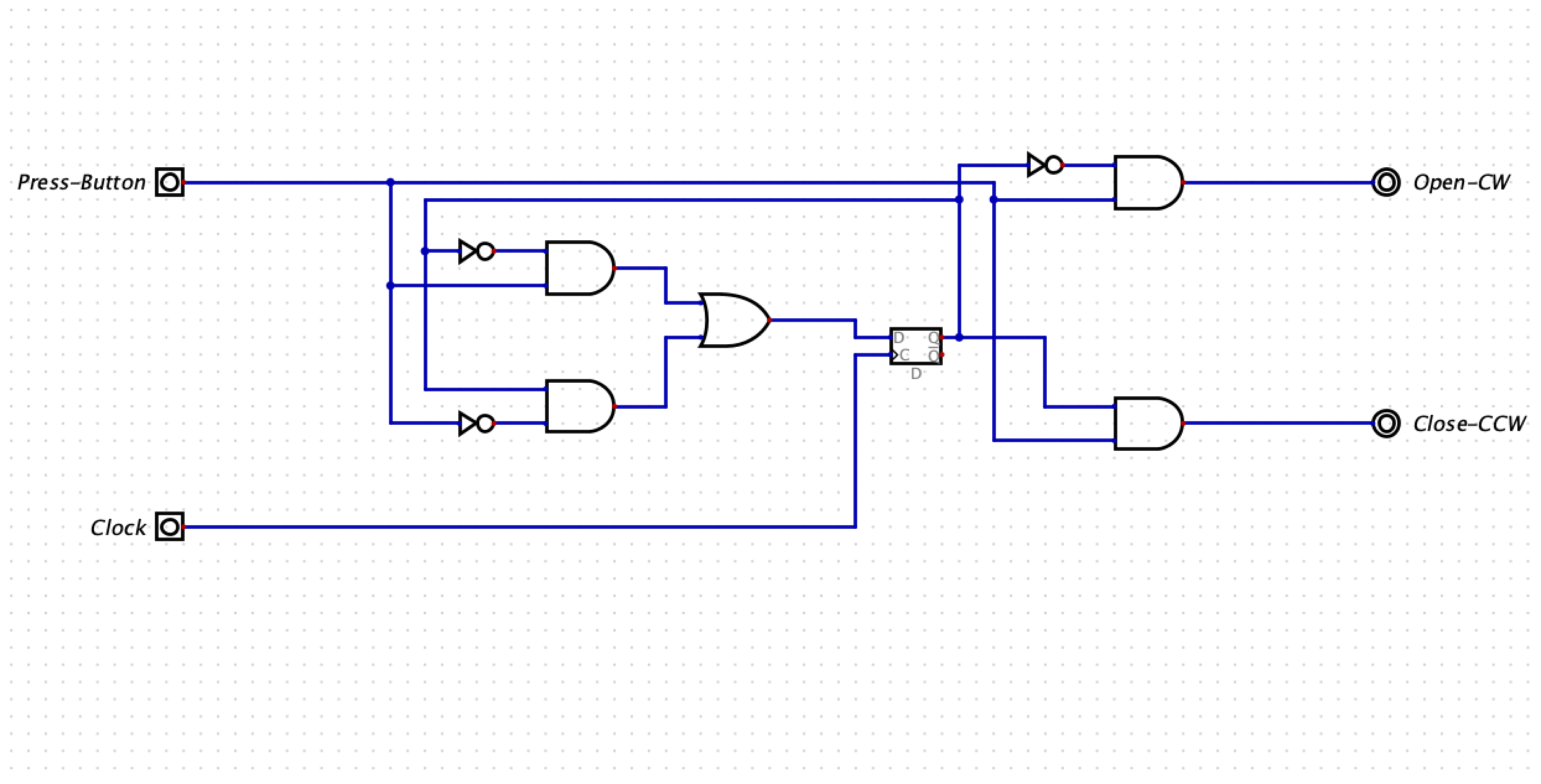
I got this circuit from the book Introduction to Logic Circuits & Logic Design with Verilog, Second Edition. It's on page 248 for reference.

enter image description here

It is supposed to be a circuit that opens or closes a window (I assume a car window).

The Open-CW output is supposed to represent a signal sent to a motor that turns it clockwise, while the Close-CCW signal turns the motor counter-clockwise.

The input Press represents if the button is being pressed.

When thinking about the behavior of the circuit, it occurred to me that if the button was held in the ON state, the output would toggle back and forth from Open-CW to Close-CCW, in sync with the Clock.

I built the circuit, as seen in the picture, and sure enough, that's what happens.

That sort of behavior doesn't really make sense to me. Why would you want your motor to toggle directions with the Clock? I think of clock signals as being automated inputs that have fixed frequencies, generally with many cycles per second. Again, why would you want your window motor to change directions that frequently?

Then it occurred to me, maybe I'm thinking about the Clock incorrectly. In this example, would it be appropriate to use some sort of lever switch located at the top of the window as a "Clock" signal. So that when the window rises fully, it engages the switch and triggers a positive edge and changes the motor direction? Similarly, place another at the bottom so that when the window is down fully, it triggers another positive clock edge and changes the motor direction again.

This functionality would make more sense to me, but is it common and/or proper to use an external input like a lever switch to act as a Clock signal? Am I misunderstanding something fundamental about clock signals?

\$\endgroup\$
3
  • 3
    \$\begingroup\$ Maybe that's just a bad example? As you said yourself, and knowing how car windows work when operated with buttons, it would not make sense to toggle the direction with the clock while button is held down. \$\endgroup\$
    – Justme
    Commented Jul 1, 2023 at 22:31
  • \$\begingroup\$ Well if this is a bad example, what are some proper use cases for FSMs? \$\endgroup\$ Commented Jul 1, 2023 at 23:22
  • \$\begingroup\$ the AND gate on the right could be eliminated and the Open-CW term obtained at the output of the top left AND gate \$\endgroup\$
    – jsotola
    Commented Jul 2, 2023 at 0:50

2 Answers 2

1
\$\begingroup\$

It is quite unusual for a clock to be anything other than a uniform frequency which serves to keep the entire system in predictable, synchronous timing.

The problem statement is hard to interpret reasonably: the window can be going up, going down, or stopped. How is a single button supposed to meaningfully select between these? Your system has only a single bit of memory: it can either be "on" or "off", but how does that map to the three possible states of the motor? The system has no indication whether the window has reached the limits. Maybe the clock is regulating some regular cycle between up/down, or represents the time it takes to run the motor from one end to the other, but this seems unnatural.

\$\endgroup\$
0
\$\begingroup\$

Many examples in logic design are contrived and do not make practical sense. In reality you have to deal with button bounce behavior. But if the clock rate was something like 0,2Hz, then maybe it might make sense.

But the point is you were able to figure out what the functionally was doing, so maybe it served its purpose.

\$\endgroup\$

Your Answer

By clicking “Post Your Answer”, you agree to our terms of service and acknowledge you have read our privacy policy.

Not the answer you're looking for? Browse other questions tagged or ask your own question.