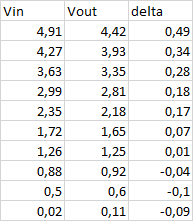
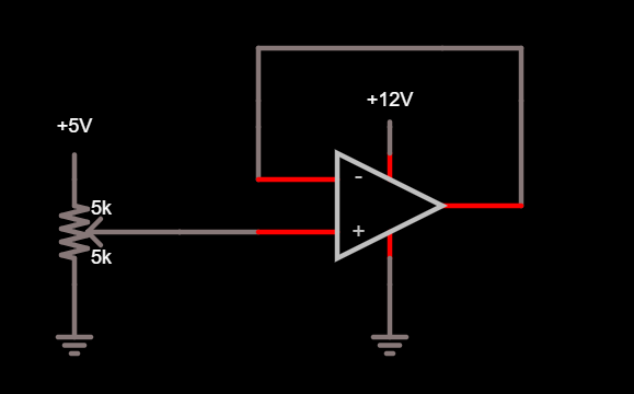
I have a voltage follower with LM358. Supply voltage is 12V. Input voltage is taken from 10k digital potentiometer. No load connected to the opamp output. In the table you can see the input and output voltages. I cannot understand why the output voltage progressively goes lower than the input voltage despite that Vin/Vout are far away from the positive supply rail. Any ideas?
-
3\$\begingroup\$ Are you using the same meter for input and output or two different meters? \$\endgroup\$– Spehro 'speff' PefhanyCommented Jul 2, 2023 at 13:18
-
7\$\begingroup\$ Can you draw the exact circuit, with supplies and everything, and add it to the question using the schematic tool in the editor? This is weird behaviour, and I'm sure you understand that it's hard to trust a beginner when he/she says "I built such-and-such". \$\endgroup\$– Simon FitchCommented Jul 2, 2023 at 14:12
-
3\$\begingroup\$ Maybe supply is noisy or op-amp is unstable due to missing bypass caps. But as the connections are unknown we should see them first. \$\endgroup\$– JustmeCommented Jul 2, 2023 at 14:19
-
\$\begingroup\$ @Spehro Pefhany - yes, I'm using the same meter, switching between input and output. \$\endgroup\$– irilinirCommented Jul 2, 2023 at 18:14
-
\$\begingroup\$ @Simon Fitch I added the circuit in the main post. 5V and 12V comes from different power sources (DC-DC buck convertors) with connected grounds. By the way, it is true that I'm not a pro in electronics, but I have high school and bachelor degree in communication techniques and technologies plus 17 years work experience in embedded software devellopement. 100nF cap between Vcc and ground doesn't change anything. \$\endgroup\$– irilinirCommented Jul 2, 2023 at 18:40
3 Answers
Since the successor LM358B is specifically touted as being unity-gain stable, you might be experiencing oscillation with the LM358. You might also see a bit of offset from the bias current; putting a resistor into your feedback path might reduce this. A 10k pot will have a maximum impedance of 2.5k on the tap, so a handwavy 1.2k will be a compromise value (a digital pot as a voltage source has its downsides). You may want to bypass that resistor with 47pF or so in order to keep it from creating an oscillator with the input capacitance.
While adding capacitors, don't forget to add 100nF bypass capacitors from the power pins of the LM358 to the ground plane.
-
\$\begingroup\$ TI's LM358 datasheet specifically calls the B variant unity-gain stable, but ST's datasheet claims unity-gain stability for the A and no-suffix variants as well, and Diodes's has "Internally frequency compensated for unity gain" in the headline features section for the no-suffix variant. They both even show them being used as unity-gain buffers in their typical applications sections. \$\endgroup\$– HearthCommented Jul 4, 2023 at 15:51
I wired up a quick breadboard circuit using LM358N DIP. Power is unregulated 13V with ripple, bypassed with 1uF and 100nF. A-Out (1) connected to A-Inverting (2) as unity-gain non-inverting amp. B-Inputs grounded. A-Non-inverting input (3) connected to 10K pot wiper supplied w/5 volts regulated, also adequately bypassed. As pot was adjusted from 0 to 5V, output tracked input within a millivolt or so. Your issue could be:
- Circuit not wired correctly
- Bad LM358
- Using low-impedance meter (VOM). This can cause your input voltage to change. When you move the meter from input to output (or vice versa), your input voltage changes.
-
\$\begingroup\$ tried to bypass the power supply with 100nF and 4.7uF, no change. Tried to ground 2 inputs of unused amp - no change. Tried with the other amp - same. But - when I use two different meters, they measure the input within 2-3mV (4.90-4.93), but the output is within 13mV (4.55 - 4.68). Measured the resistance if the first meter with the second meter and gives me 1MOhm. \$\endgroup\$– irilinirCommented Jul 2, 2023 at 20:16
-
\$\begingroup\$ When the circuit is powered by a lab supply it works well, even the output is little higher than the input. But when is powered by the DC-DC buck convertor it doesn't. I tried to add 100nF and 220uF between Vcc and ground, bit it doesn't help \$\endgroup\$– irilinirCommented Jul 2, 2023 at 21:03
There’s AC on the output - whether it’s instability or supply noise or what, hard to tell. But that’s how typical LM358 behaves when it’s got on the order of 100kHz of junk on the output. It’s not very DC accurate then.
But it’s a fairly docile part so working as a follower it should have no trouble at DC if the output isn’t capacitively loaded.
-
\$\begingroup\$ Is it possible to be because I use DC-DC step down convertors as power supply? They are using XL4015, which work on 180 KHz. Or some noises from the digital potentiometer. First i tried to use it (the dig. pot.) in the feedback loop of another opamp (inverting amplifier used as feedback circuit for current control of a voltage regulator), but the result was very unstable, so I gave up with the idea. \$\endgroup\$– irilinirCommented Jul 2, 2023 at 18:49
-
\$\begingroup\$ edit - it is not from the digital potentiometer. With normal behaves the same. \$\endgroup\$– irilinirCommented Jul 2, 2023 at 19:50
-
\$\begingroup\$ it seems that you were right. When the circuit is powered by a lab supply it works well, even the output is little higher than the input. But with this DC-DC buck convertor it doesn't. I tried to add 100nF and 220uF between Vcc and ground, bit it doesn't help. \$\endgroup\$– irilinirCommented Jul 2, 2023 at 21:02
-
\$\begingroup\$ and the funny part - when I touch the ground, the voltage on the output goes to normal value. \$\endgroup\$– irilinirCommented Jul 2, 2023 at 23:02


