1
\$\begingroup\$

I am currently working on an LED clock project, and one of the things I would like to use is the SMDs found in WS2812B neopixel. I could simply use the LED strip itself, but I wanted to use a custom setup for the SMDs, so I thought about designing the PCB. However, I don't have a lot of experience designing PCBs, so I'm not really sure if I'm doing things correctly.

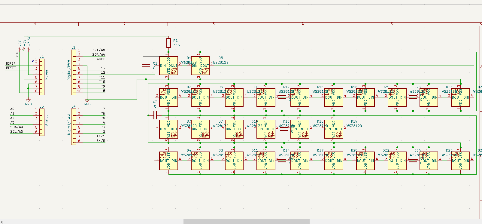
The schematic for the PCB I envisioned it to be. It may look like a matrix, but it's supposed to be a linear strip.

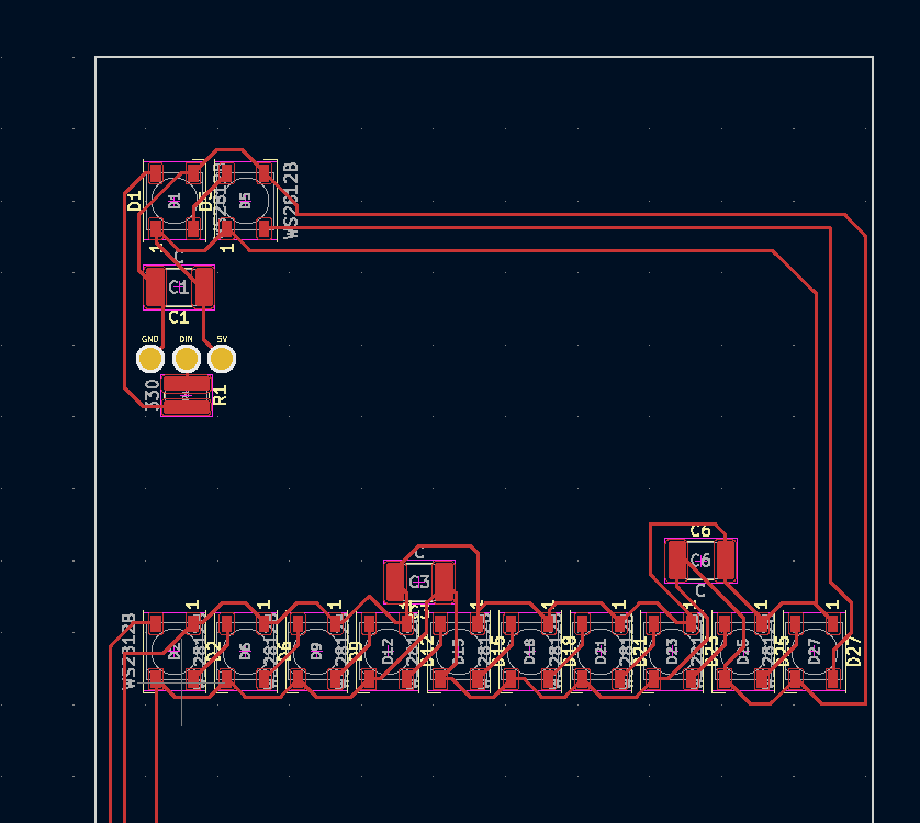
The top half of the PCB I came up with where it includes the start of the "strip"

So I wanted the LED to be arranged in a zig-zag way that starts from the top left. I included the resistor (330 Ω) at the beginning and I connected a capacitor (supposedly somewhere between 100 to 1000 uF) to one of the SMDs for every 4 SMDs (I asked for suggestion from someone who knows PCB way better than I do, and he suggested that it's probably fine to have 1 for every 4 SMDs).

I would have bought a sample or 1 one of this board to test out and fix whatever I did wrong, but I am currently short on time, so I'm hoping I could get some help in getting feedback on what I did wrong before ordering the PCB.

\$\endgroup\$
5
  • 1
    \$\begingroup\$ Did the board not function? In what manner? In other words, how do you know it is 'wrong'? \$\endgroup\$
    – JYelton
    Commented Jul 24, 2023 at 18:00
  • \$\begingroup\$ I haven't tested it yet, but I'm a bit skeptical with the way the PCB is designed. \$\endgroup\$ Commented Jul 24, 2023 at 18:19
  • 1
    \$\begingroup\$ What is the purpose of R1 - 330 ohm? It will be carrying the total current of all the LEDs. If it is intended to limit the LED current, you really need one 330 Ohm resistor in series with EACH LED, not one in series with the whole bunch. \$\endgroup\$ Commented Jul 24, 2023 at 18:56
  • \$\begingroup\$ C3 and C6 look kind of poorly laid out. You've got two sides to your board--use them both! \$\endgroup\$
    – Hearth
    Commented Jul 24, 2023 at 19:27
  • 1
    \$\begingroup\$ @PeterBennett, these are addressable LEDs. You wouldn't need a resistance at all from my understanding. \$\endgroup\$
    – Julien
    Commented Jul 24, 2023 at 20:15

2 Answers 2

2
\$\begingroup\$

Here are some quick advise: Your traces seems a bit small, considering the freespace you have. They are also very long for their width. R1 is quite close to the header. The decoupling capacitors only work if the impedance of your power is good. In that instance, it is pretty bad.

Honestly, I think your schematic has a lot more issue. For instance that series 330ohm resistor seems very odd to me. I really don't want to be insulting in any way, but I think you should really consider extending your deadline and doing a small batch first to ensure that it is functional before production. Sorry

\$\endgroup\$
3
  • \$\begingroup\$ The 330 ohm resistor is meant to go on the data line to limit rise time. He seems to have transposed it by mistake to the power line. \$\endgroup\$ Commented Jul 25, 2023 at 1:11
  • \$\begingroup\$ Well, that's my point. You don't own enough your design to skip prototyping. I didn't do a full design review on your board and it took me less then a minute to find a mistake. \$\endgroup\$
    – Julien
    Commented Jul 25, 2023 at 1:23
  • \$\begingroup\$ I guess also the resistor is meant to go near the source of the signal (before the transmission line), not the load, so probably not necessary on the board. \$\endgroup\$ Commented Jul 25, 2023 at 2:26
1
\$\begingroup\$

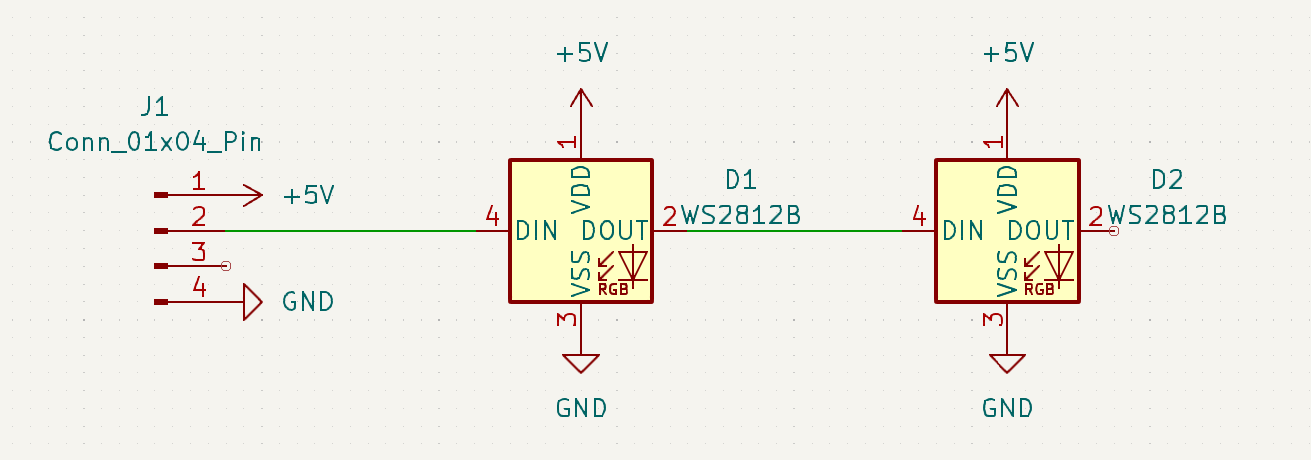
First, clean up your schematic so you can see what you're doing and spot mistakes like the misplaced 330 ohm resistor. Rather than a maze of wires, use labels for common things like power and ground:

enter image description here

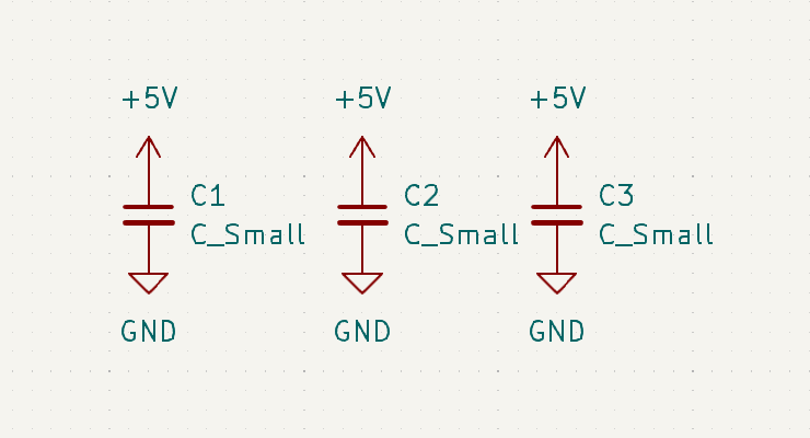
This makes the data line much more clear and easy to follow. In addition, put the capacitors off to the side with labels:

enter image description here

Now they're not on top of your digital logic. If you were going to use a lot of LEDs, Kicad's hierarchical sheets also let you build circuit blocks composed of other circuits, for example a block representing 16 LEDs. This can help you avoid the need to copy hundreds of the same element over and over again, although in this case you may not need them.

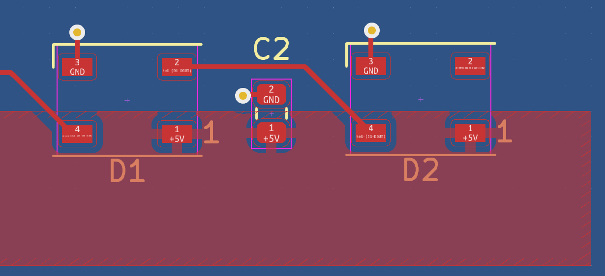
With respect to the PCB layout, you need more copper in your traces, especially if you're going to have a lot of bright LEDs all run off a single line. Instead, consider using planes which have much lower resistance:

enter image description here

Note that you can also use both sides of the board, so I've made the back a ground plane.

Finally, I'm not sure putting the 330 ohm resistor at the load helps. I think it should have been at the source of your digital signal otherwise you will still generate reflections if the line is very long.

\$\endgroup\$

Your Answer

By clicking “Post Your Answer”, you agree to our terms of service and acknowledge you have read our privacy policy.

Not the answer you're looking for? Browse other questions tagged or ask your own question.