A current-mode power converter is usually compensated with a type 2 compensator. Whether it is done with a classical op-amp or an operational transconductance amplifier (OTA) as in this LT part does not modify the discussion. This type 2 will introduce a pole at the origin (the integral part) and a zero-pole pair. The distance between the zero and the pole sets the amount of phase boost necessary to meet the phase margin requirement. Usually, the crossover frequency is selected at the geometric means of the pole and zero where the phase boost peaks: \$f_c=\sqrt{f_zf_p}\$
In the below picture, I have plotted the control-to-output transfer function of a buck operated in current mode and continuous conduction mode or CCM. This transfer function is excerpted from my last book on the subject. I also did include the transfer function of the type 2 compensator and the multiplication of the two transfer functions in the Laplace-domain leads to the open-loop gain you want to study:

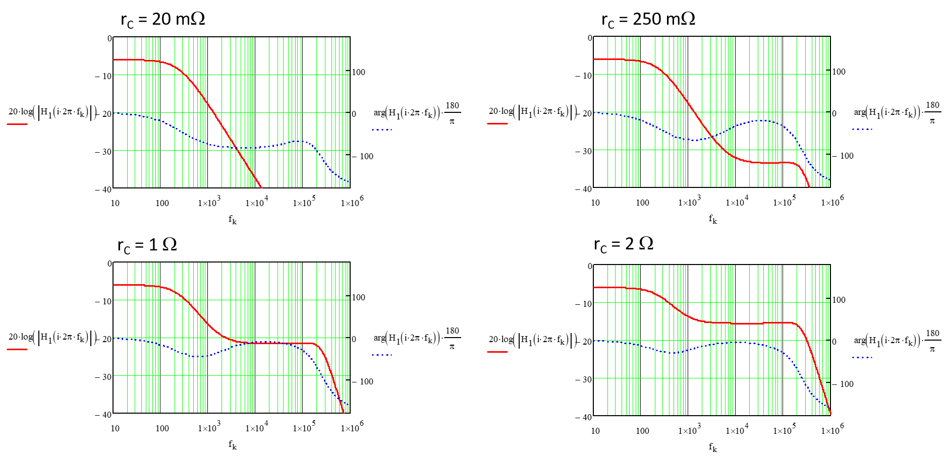
In this example, the equivalent series resistance of the capacitor (ESR) sets a zero at 6.3 kHz. If we consider the current-mode buck converter as a 1st-order system in the low-frequency portion (before the subharmonic poles), then you start with a dc gain (depending on the sense resistance, the amount of slope compensation etc.), then follows a -1-slope owing to the pole and, when the ESR zero kicks in, the magnitude flattens out to a 0-slope. You see the effect with the phase response first going down towards -90° and then going back to 0° because of the ESR zero. Later on, at \$\frac{F_{sw}}{2}\$, the double poles show up and break the magnitude to -2 again, pushing the phase down to -180°.
If you set the compensation zero at 2.5 kHz and the pole at 10 kHz, then you can crossover at an arbitrarily-selected frequency of 5 kHz and enjoy a good phase margin (76°) with a robust gain margin of 34 dB or so.
Now, if I push the zero to lower frequencies, the phase margin increases but the type 2 response is no longer that of an integrator with a narrow magnitude window at crossover, but it flattens out significantly because of the zero popping up well below crossover and breaking the -1-slope from the pole at the origin. You no longer firmly crossover at 5 kHz but in a more "lazy" way:

As an effect, you do not firmly roll off the gain after crossover (the compensation is flat) because pushing the zero down also pushes the pole up. As a result, the gain margin suffers - even if it still high in this example - and you may have problems if big gain variations are expected. Another effect of pushing the zero too low, beside slowing down the transient response, is the loss of loop gain at low frequency, directly impacting the rejection capability of the power stage at these low frequencies.
You have a similar issue if the ESR of the capacitor becomes too high: the power stage gain flattens out way sooner than with the a low ESR:

With a 2-ohm ESR and the zero set at 250 Hz, the gain margin is now 14 dB, way smaller than before.
These examples purposely use extreme values but you can see the effects of having too low a zero or too high an ESR. I would not rely on a formula but actually either use equations as I did or run an ac simulation - for instance taking advantage of my free ready-made templates - and see, once the compensation strategy is adopted, how varying the ESR between its min and max affects margins.


