0
\$\begingroup\$

I have some questions about this small project, a device to detect bat ultrasounds and reproduce in a speaker. It's based in a post of the Element14 community, Episode 578. I have adapted it and I'm testing in a breadboard. It somehow works but not very well, it's unstable and lossy. Here is my schematic: Bats ultrasounds detector
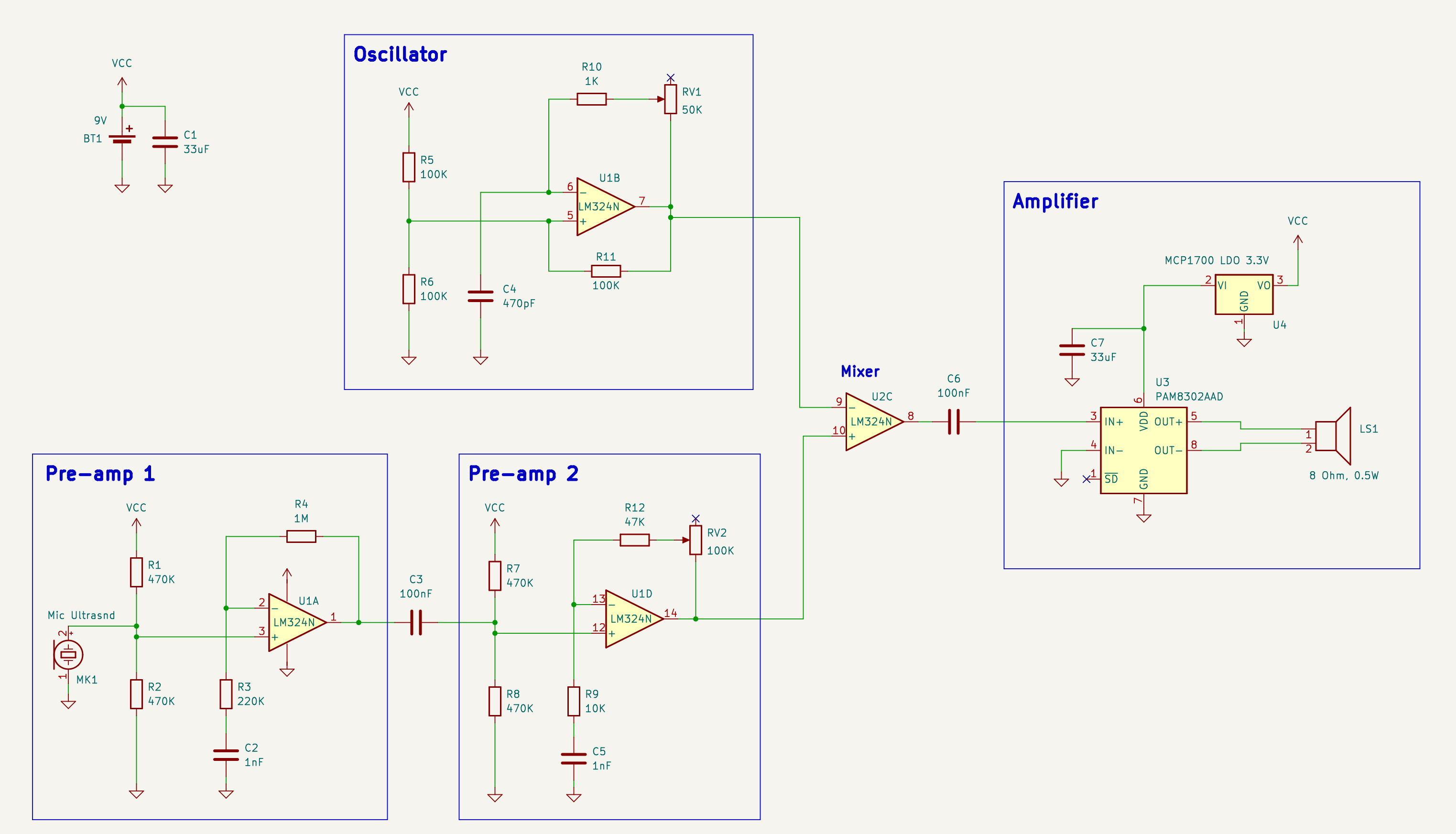
This is my understanding of the concept. Bats emit ultrasounds to navigate and locate insects for dinner, in different frequencies from 20 KHz to more than 100 KHz depending on the specie. Humans can hear in the range of 20 Hz to maximum 20 KHz, so we need to transform the signals. To do this I use a ultrasounds sensor and the 4 op-amps in the LM324N package. Two of them for two pre-amplification stages. I suppose that it is because the LM324 has not a high gain for the range of frequencies around 50 KHz.

Then there is an oscilator with a potenciometer that produces a wave adjustable between 12 KHz and 90 KHz aprox. I mix this wave with the 'bats signal' to get a heterodyne signal with all the combinations of the frequencies: separated, added and substracted. We are interested only in the substracted signal, the others will be higher and can be filtered. For example, if a bat is emiting at around 40 KHz and I adjust the oscillator to 35 KHz, the substration will result in a signal of around 5 KHz. Then this signal is sent to a power amplifier and speaker.

The microphone nominal frequency is 40 KHz, I don't know which usable range it has. Sound quality is not important as you hear mainly 'clicks' time to time when the bats are near.

After a lot of debugging it works, I can hear the 'clicks' of the bats, but it's quite unstable. As the bats are not always willing to collaborate, for testing I move a key-ring in front of the sensor, it produces many frequencies.

I'm not sure if it is working properly or could be improved. I have some doubts:

  • The pre-amps should filter the frequencies below 20 KHz. Is this done by C3? Or by C2 and C5? they look to me like a low pass filters to remove noise
  • I check the oscillator with the oscilloscope in the frequency domain. It produces a kind of triangular signal with a main freq but several higher peaks separated about 20 KHz. If I move the potenciometer it goes from 12.5 KHz to 90 KHz and the other peaks move also, sometimes there are less. In theory it should be a single square wave, right?
  • At the output of the pre-amp stages there is always a constant signal of 55 KHz and about 280mV in the 2nd stage. It's only a bit smaller than the mic signal, I don't know if this comes from the mic itself. When I connect the probes directly to the microphone the oscilloscope introduces more noise.
  • I don't know if the rest of higher frequencies go to the speaker and could disturb the bats, after the mixer I see freqs in all ranges. Maybe the amplifier and the speaker aren't able to manage those freqs anyway. In the output of the amplifier I can't see it clear.

I would like also to be able to identify at which frequencies actually emit the bats. I guess that it is around 40 KHz, but I'm not sure. Any hint on improving it or testing would be very helpfull.

Thank you!

\$\endgroup\$
4
  • 1
    \$\begingroup\$ Perhaps unwise to use the class-D PAM8302 audio amplifier - it is also an ultrasonic generator. Better to use old-school linear amplifier here like LM386 or equivalent. \$\endgroup\$
    – glen_geek
    Commented Jul 30, 2023 at 11:34
  • \$\begingroup\$ Ok, I was not aware. Acually I will get some LM386 soon and I will replace it. Then I don't need the LDO neither. \$\endgroup\$
    – Gos
    Commented Jul 30, 2023 at 12:50
  • \$\begingroup\$ That piezo microphone is suspect. If it is a common ultrasonic 40kHz transducer, it is sharply resonant near 40 kHz making it less-sensitive at other ultrasonic frequencies. You might be able to extend its bandwidth with an RL network. It may be better to drive a proper multiplying mixer from the microphone, then amplify the mixer's audio output. Some active multiplying mixers have gain. I'd suggest a SA612 mixer from NXP \$\endgroup\$
    – glen_geek
    Commented Jul 30, 2023 at 13:52
  • \$\begingroup\$ A lousy old LM324 is not used for audio because it does not produce high audio frequencies so you need a better opamp since most audio opamps operate fine up to at least 100kHz. The 40kHz piezo transducer produces ONLY 40kHz. The breadboard causes high frequency oscillation instead of amplification. \$\endgroup\$
    – Audioguru
    Commented Jul 30, 2023 at 17:35

3 Answers 3

3
\$\begingroup\$

Any hint on improving it or testing would be very helpful.

You need a proper mixer (multiplication) and not an audio-type filter (linear addition) if you are going to successfully convert ultrasonic sounds to within the human hearing range with decent sensitivity and accuracy.

Maybe if sufficiently overdriven the LM324 inputs can form a crude multiplier but, at best it will be insensitive and unreliable.

I check the oscillator with the oscilloscope in the frequency domain. It produces a kind of triangular signal with a main freq but several higher peaks separated about 20 kHz. If I move the potenciometer it goes from 12.5 kHz to 90 kHz and the other peaks move also, sometimes there are less. In theory it should be a single square wave, right?

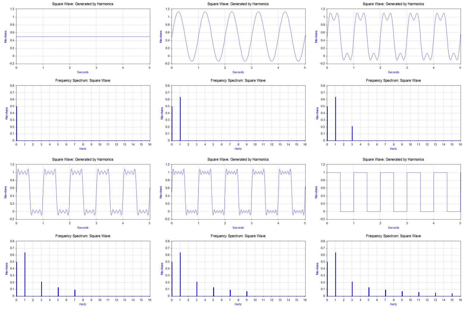
A square wave or triangle wave naturally produces harmonics. That is what you are witnessing. Only a sinewave produces no harmonics. Square wave from wiki: -

enter image description here

Also, due to the harmonic content, a square wave may not be as useful as a sinewave when converting to baseband.

At the output of the pre-amp stages there is always a constant signal of 55 kHz and about 280mV in the 2nd stage. It's only a bit smaller than the mic signal, I don't know if this comes from the mic itself. When I connect the probes directly to the microphone the oscilloscope introduces more noise.

That sounds like a bad PCB layout problem or, maybe you are fouling things up using breadboard?

\$\endgroup\$
12
  • \$\begingroup\$ Ok, I can change the mixer. Checking about it I think that you are rigth, it should be a multiplier. About the harmonics of course you are right, I didn't realize. You need a lot basic waves to produce a square or triangle signal. \$\endgroup\$
    – Gos
    Commented Jul 30, 2023 at 12:58
  • \$\begingroup\$ For the mixer something like the AD633 would be fine? Just from a quick google search, I haven't look at the details yet. And about the PCB, yes, there could be still problems. Actually it's a nightmare to work with the breadbroad. I have spent a lot of time checking the connections, you are never sure that all contacts are working, specially for resistors. \$\endgroup\$
    – Gos
    Commented Jul 30, 2023 at 13:09
  • \$\begingroup\$ @Gos that's the sort of device that should work better but, if the original design (that you base your circuit on) uses something else then why not use that. If we are done here, please take note of this: What should I do when someone answers my question. If you are still confused about something then leave a comment to request further clarification. \$\endgroup\$
    – Andy aka
    Commented Jul 30, 2023 at 13:12
  • \$\begingroup\$ In the original design is doing the same, with small differences in the resistors values. Could be that it works only partially and because some frequencies end by chance in the lower range producing the clicks? \$\endgroup\$
    – Gos
    Commented Jul 30, 2023 at 13:25
  • \$\begingroup\$ I have no idea about the original design because I cannot access it. \$\endgroup\$
    – Andy aka
    Commented Jul 30, 2023 at 15:22
1
\$\begingroup\$

schematic

simulate this circuit – Schematic created using CircuitLab


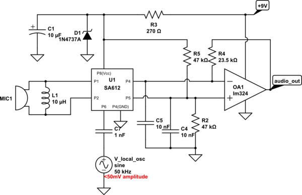
A piezo microphone can go directly to mixer input pins (1,2). The inductor L1 might require a different value depending on piezo characteristics. Its purpose is to broaden bandwidth of a piezo transducer. The SA612 shouldn't be supplied with DC voltage over +8V.

Local oscillator sine wave can be applied to pin 6. If amplitude is too high, the mixer begins to respond to odd-order harmonics. However, gain increases when you drive pin 6 with amplitudes up to 300mV.
Construction must be done with care - this mixer is sensitive to many hundreds of Megahertz.

Another stage of audio amplification might be needed. OA1 is a differential amplifier...R4 = (R5*R2)/(R5+R2).

\$\endgroup\$
4
  • \$\begingroup\$ Great! That's another level! I will check, it seems not very complicated, but I'm just a hobbist. My doubt would be how to get the sine oscillator. A op-amp view bridget would be ok? \$\endgroup\$
    – Gos
    Commented Jul 30, 2023 at 15:50
  • \$\begingroup\$ Perhaps a Wien bridge oscillator, or phase-shift oscillator. Making them variable-frequency adds complication. SA612 only needs small amplitude, and very little current at its local oscillator port at pin 6, making the oscillator a bit easier. A larger amplitude and square wave here will still "mix", but has disadvantage that Andy has pointed out. \$\endgroup\$
    – glen_geek
    Commented Jul 30, 2023 at 18:02
  • \$\begingroup\$ I will try your proposal, it looks clever and neat. In some days I'll get some SA612 and also some NE5532P, AD633. They are cheap anyway. Meanwhile I'll experiment the Wien bridge and phase shift oscillators. Thanks! \$\endgroup\$
    – Gos
    Commented Jul 31, 2023 at 16:20
  • \$\begingroup\$ The SA612 actually does have a built-in oscillator transistor - you'd have to add an inductor and three capacitors. This oscillator presents difficulty because the inductor value and/or capacitor values are difficult to change to make it variable-frequency. Any sine-wave oscillator is difficult to make tuneable, be it Wien, phase-shift, or LC. You might want to first try that simple, tunable square-wave RC oscillator first to get a feel for the need for tuneability. Amplitude sent to SA612 pin #6 should be less than 300mV. \$\endgroup\$
    – glen_geek
    Commented Jul 31, 2023 at 20:57
1
\$\begingroup\$

Finally I got some parts and some time and I have also found more information in the direction of using the SA612 as @glen_geek suggested.

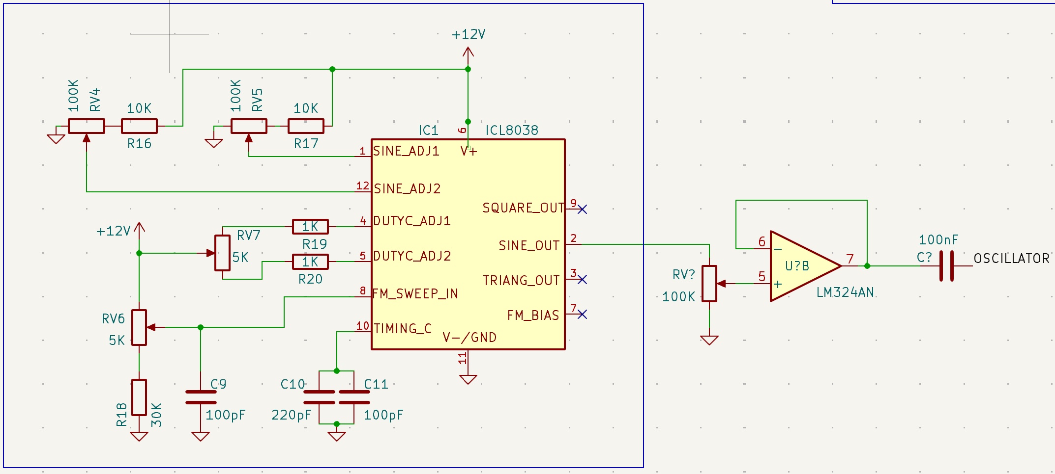
I'm using a ICL8038 to generate an adjustable sine wave from about 15KHz to 100Khz. For what I have been reading a square wave should also work. I have reworked part of a pcb from a kit: oscillator With the last potentiometer I reduce the amplitude to 200mV. It is constant all the range.

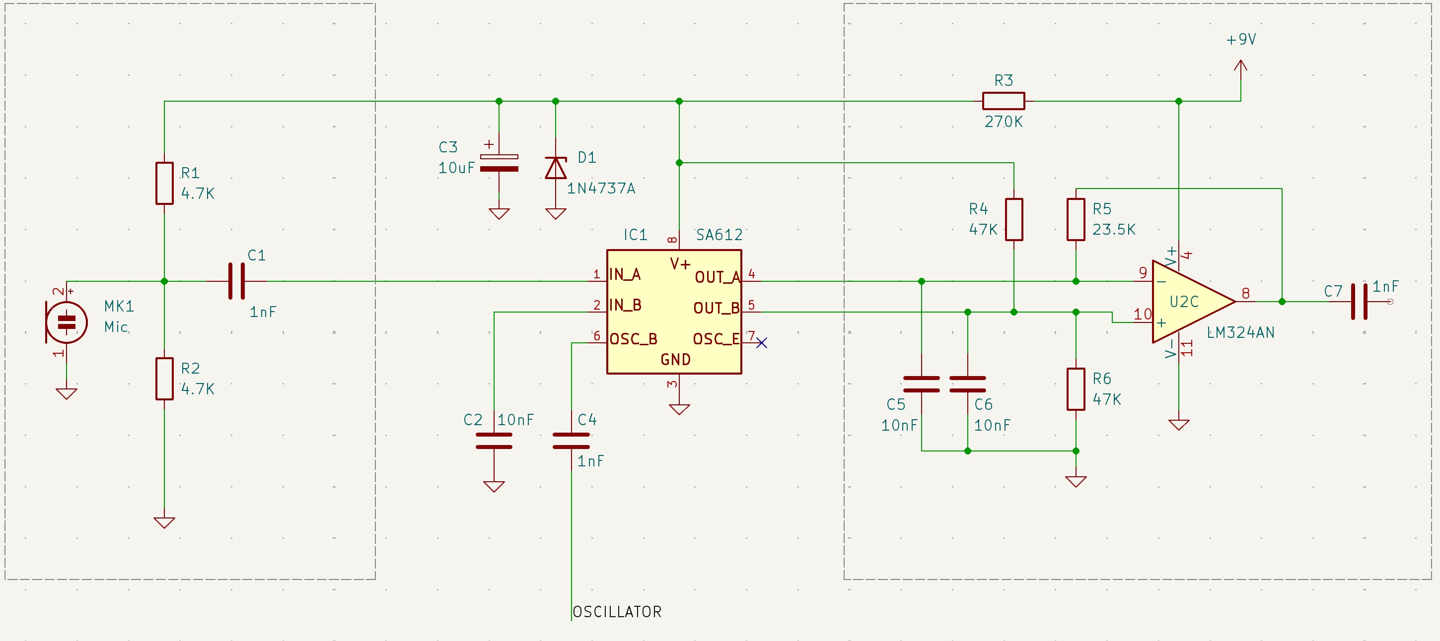
And the circuit that I'm working on: enter image description here

Here: https://www.teensybat.com they are working in this kind of devices since years ago. This could help other people looking for information about bat detectors.

They have a similar version: https://www.teensybat.com/simple-heterodyne-fd and have also a nice one with a MCU, mini audio card overclocked to work up to 100KHz, display, etc. They have a lot of resources, information, detailed explanations, hints, other approaches like the freq divisor, etc. For example: http://bertrik.sikken.nl/bat/ne612het.htm

I think I will have to work in the noise and interferences, maybe move to a soldered board.

\$\endgroup\$

Your Answer

By clicking “Post Your Answer”, you agree to our terms of service and acknowledge you have read our privacy policy.

Not the answer you're looking for? Browse other questions tagged or ask your own question.