1
\$\begingroup\$

I have a breaker that controls current powering a set of seven desktop computers and monitors. Sometimes it can take me up to twenty attempts to bring the breaker up. Eventually it stays up and the system is functioning well and never ever trips the RCCB.

My first reaction was that there was some sort of an electrical issue, but I have been convinced that this was due to an 'inrush current' caused by PSUs within the PCs. I have also been pointed at the article that suggested that this current can be up to 30 times that of the current drawn during normal operation. The implication is that my attempts to bring up the breaker "charge up" some internal circuitry and eventually the 'inrush current' comes in line with what the RCCB is designed to handle. The other implication is that the only way to work around the problem is to use high-quality PSUs that don't suffer from this issue.

Questions:

  1. Why does the RCCB eventually stay up?
  2. Is there not a way to design the electrical layout that would avoid this situation, apart from adding more RCCBs or adding a single one that can handle 30x the current?
\$\endgroup\$
2
  • 2
    \$\begingroup\$ Normal? It’s something you don’t want to do. Devices with high inrush/startup currents can cause what you describe and for loads like motors there are circuit breakers with different response curves. In my part of the world Class C breakers are the ‘usual’ breakers. You can use Class D for motors and loads with high startup currents. You’d have to consult a local electrician to see if such a thing is a legal and valid solution to your problem. You’d want to rule out other causes like moisture that might accumulate and cause a leakage trip. Once it gets zapped a few times burns it off. \$\endgroup\$
    – Kartman
    Commented Jul 31, 2023 at 12:25
  • \$\begingroup\$ @Kartman I know, it didn't feel like the right thing to do, but I know nothing about electrical engineering. It's great to learn that there are different response curves! I'll discuss this with people responsible. Thank you for the tip! \$\endgroup\$
    – Tony Sepia
    Commented Jul 31, 2023 at 12:28

3 Answers 3

1
\$\begingroup\$

An RCCB device would have one sensor for excess residual current (ground fault or GFCI), probably in the order of 5-30 mA, while another sensor for mains current, typically 15 or 20 amps for North American 120/240 VAC.

The answers given above should narrow down the cause of the tripping. One fairly likely culprit is the front end of the switching power supplies, which consist of a rectifier and fairly large capacitor. In this case, each time you attempt to reset the breaker, the capacitor(s) eventually charge up to a level where subsequent off/on attempts do not experience such surges.

Also, repeated operation of a circuit breaker, especially under heavy (and especially reactive) loads, will cause degradation of the contacts, resulting in arcing and heating. It would be much better to use a separate switch to turn off/on the power supplies. A ZC triac or SCR relay may be a good idea.

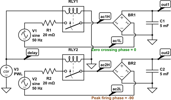
(edit) This simulation shows the advantage of using a zero crossing contactor to reduce turn-on current into a capacitive load.

schematic

simulate this circuit – Schematic created using CircuitLab

Currents

Voltages

\$\endgroup\$
4
  • \$\begingroup\$ Sorry, could you please elaborate on how could the ZR Triac or SCR relay be used to help the situation? \$\endgroup\$
    – Tony Sepia
    Commented Aug 1, 2023 at 9:17
  • 1
    \$\begingroup\$ A ZC triac or SCR will apply voltage starting at the zero crossing, so there will be about 4-5 ms before the peak voltage is applied. Maybe I can add a simulation to my answer. However, it might not help if the ground fault or residual current element is tripping. \$\endgroup\$
    – PStechPaul
    Commented Aug 2, 2023 at 2:45
  • \$\begingroup\$ that is impressive! Thank you for sharing the design! Is this something that would usually be implemented within the PSU, or as some sort of an external unit placed immediately before the load? \$\endgroup\$
    – Tony Sepia
    Commented Aug 2, 2023 at 6:56
  • 1
    \$\begingroup\$ You will first need to determine if this is an overcurrent trip or ground fault. It could also be a failing circuit breaker. Can you install a new one? The "design" is mostly to simulate the action of a ZC solid state relay, which would be installed after the breaker, and can be controlled by a DC logic level signal. You might also try using a power factor correction (PFD) device, such as ametherm.com/blog/inrush-current/… \$\endgroup\$
    – PStechPaul
    Commented Aug 2, 2023 at 19:56
5
\$\begingroup\$

If a breaker activates as soon as you reset it, then you should NOT continue to activate it repeatedly. Such actions could cause a fire. In a worst case scenario, it could fail to start a fire immediately, but cause enough damage to your wiring that a fire begins at some point in the future.

What you should do instead, is turn off whatever loads are on that breaker's circuit, and then turn the breaker on. If the breaker still trips, call an electrician.

Next, you should sum all the rated currents for all of the loads on that circuit and make sure it it is less than the rated current for your breaker.

Then turn on the loads for that circuit one by one, making a mental note of the order in which you turn them on. If the breaker does not trip, good. However, it might well trip again soon, as you did not do anything to fix whatever caused the breaker to trip in the first place.

However, if the breaker trips when you turn the loads on one by one, then something is likely faulty. It could be one of the loads drawing more current than it is rated for, or it could be the wiring is at a fault. However, for now, you can rule out the fault being in any of the loads that are still off. For the rest of this diagnostic, don't turn any of these loads back on.

Next, turn off all the loads again. Reset the breaker. Then turn on the last three loads you turned on in the last test, but turn them on IN REVERSE ORDER from the previous time. If the breaker trips, one of the loads you turned on is faulty. Have someone qualified come and test them further.

Although it is possible for you to repeat the tests above, turn on all the potentially suspect loads in different orders, until you possibly eliminate all but one, I do not recommend it if you have more than three potential suspects. Again, there is a danger that you are damaging insulation every time you overload the circuit and trip the breaker. However, it is also possible that one of the loads is faulty enough to draw more current than it should, but not faulty enough to trip the breaker by itself. Testing using the method described might not even discover such a fault. Rather than risking damage to the wiring, it would be better to get someone qualified to test the actual current in each load. If you have a clamp ammeter, it will NOT work to simply clamp around the utility cord of appliances. Current flowing one way in the live wire will be flowing the opposite way in the neutral, and they will appear to cancel each other out in your meter. You need a special wire or device to place between the plug of your appliance and the wall socket, in order to make such a measurement. Someone qualified may have such a special wire or device, or may be able to make and use one safely.

\$\endgroup\$
3
  • \$\begingroup\$ Thank you for the detailed answer! I will study it carefully \$\endgroup\$
    – Tony Sepia
    Commented Jul 31, 2023 at 14:01
  • \$\begingroup\$ One thing you have not commented on is that everything works well once I manage to get the breaker up. What sort of a 'load fault' are we talking about if it stops to exist after we 'energise the PSUs' or whatever it is we are achieving by repeatedly engaging the breaker? \$\endgroup\$
    – Tony Sepia
    Commented Jul 31, 2023 at 16:59
  • \$\begingroup\$ @TonySepia It could be "luck" that you switched the breaker on at a particular phase of the mains voltage. You're not meant to use a breaker as a power switch. \$\endgroup\$ Commented Jul 31, 2023 at 17:46
3
\$\begingroup\$

It may be worth checking that it's not just a particular one of the PC power supply or monitors that's causing the problem, by connecting them one at a time. If the above procedure rules out a fault on one bit of kit then as @Kartman suggests, you could look at a breaker with a different curve - but a better option might be to explore using a mains filter to limit the inrush current.

\$\endgroup\$
2
  • \$\begingroup\$ Thank you for your suggestion! \$\endgroup\$
    – Tony Sepia
    Commented Jul 31, 2023 at 14:01
  • \$\begingroup\$ I'm not sure if a mains filter will effectively limit the inrush current. I think they usually have only a few mH inductance and a few uF capacitance, for TC of a few us. It might be worthwhile to try a simulation, or an actual circuit. \$\endgroup\$
    – PStechPaul
    Commented Aug 2, 2023 at 3:55

Not the answer you're looking for? Browse other questions tagged or ask your own question.