0
\$\begingroup\$

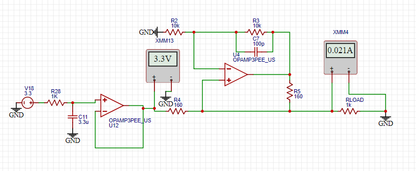
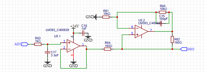
I'm fairly new to designing circuit boards. I have built a circuit in EasyEDA that takes a 0-3V3 PWM signal from a Teensy4.1 MCU and converts the signal to 0-20 mA current using a low pass filter and a Howland voltage to current converter with a LM358. The circuit does exactly what I want it to do in the simulation, however with a different opamp that's available in the EasyEDA simulation program. The LM358 is powered with 24 V single supply. I have now received the finished PCB and have started to do some testing.

Problem: When I connect power to the board the board draws enormous amounts of current, 0.6 A at 2 V and the LM358 gets very hot. I have disconnected the LM358 from the circuit and now the power supply is working properly. Also I can't test the signals in the circuit since the power supply isn't working.

If anyone has an idea of what the problem is I would be very glad to receive some pointers.

Simulation

Schematic that's implemented in the PCB

\$\endgroup\$

1 Answer 1

4
\$\begingroup\$

Well, the elephant in the room is that your supply voltage is connected with the wrong polarity on the opamp: pin 4 is its negative supply voltage pin, pin 8 its positive one. You wired it up the other way round. By the way, I am surprised that the simulation worked with the LM393 which is not an opamp but a differential comparator. Apart from that, it would also go up in flames with the supply voltage connected like that.

\$\endgroup\$
5
  • \$\begingroup\$ Thanks you very much I love you \$\endgroup\$
    – Lukas
    Commented Aug 1, 2023 at 10:10
  • \$\begingroup\$ Also, the load resistor is shorted by the ammeter @Lukas. It should be in series. \$\endgroup\$
    – user319836
    Commented Aug 1, 2023 at 15:13
  • \$\begingroup\$ @RussellH Well, in the simulation. I didn't bother saying so because the output is supposed to be a current output and connecting the amperemeter there will shorten out the load resistor, making the whole current go through the meter. Meaning that it should show the correct current, even if that's not representative for load resistances above 0 ohm. And, well, would only work in the unrealistic simulation where 0V inputs are fine. That's more like the mouse in the room. You have to get the elephant out first. \$\endgroup\$
    – user107063
    Commented Aug 1, 2023 at 15:19
  • \$\begingroup\$ I know I have shorted the load, but when I searched for the howland circuit is says that the output current would be constant no matter the load, but it did not work when I connected it in series. So do you have any suggestions on how I could drive a constant current through a single port without knowing the load? \$\endgroup\$
    – Lukas
    Commented Aug 2, 2023 at 16:44
  • \$\begingroup\$ @Lukas At one point of time you need to stop believing that opamps can do magic. 21mA·1kohm = 21V, meaning that you expect U2 to output 42V in your test circuit while being powered with 20V. The output of opamps, particularly of old opamps like the LM358 can only be driven to several volts within the power rails. You need to choose both opamp and supply voltages according to the range of output voltage and current you need. If necessary, adding discrete parts doing the heavy lifting under the opamp's control. \$\endgroup\$
    – user107063
    Commented Aug 2, 2023 at 17:15

Your Answer

By clicking “Post Your Answer”, you agree to our terms of service and acknowledge you have read our privacy policy.

Not the answer you're looking for? Browse other questions tagged or ask your own question.