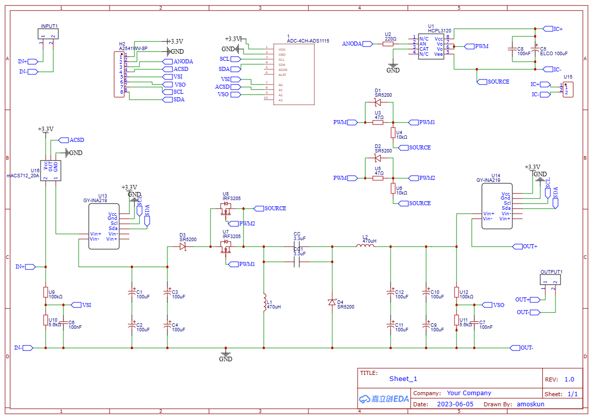
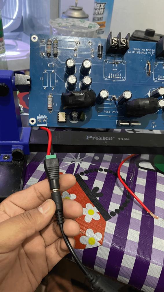
Currently, I'm designing Zeta Converter for my projects and I made this design. 
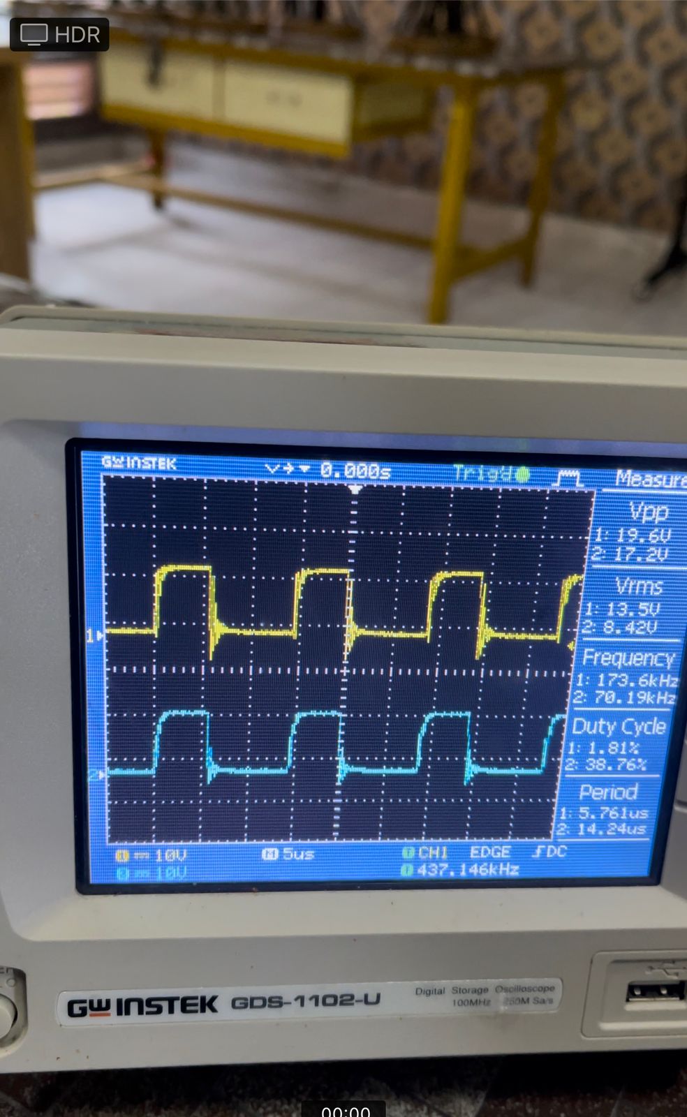
When there is no supply applied to the zeta converter, the PWM signal seems good.

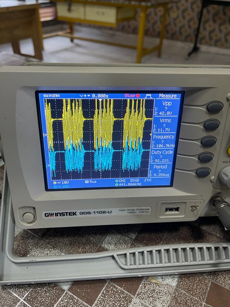
But it ends up getting a bad turn-off signal
like this picture when the supply applied

edited: so each channel are connected to PWM1/PWM2 & SOURCE to see how PWM signals are. PWM1/PWM2 are connected to the GATE of MOSFETS and SOURCE are connected to the SOURCE of MOSFETS

