0
\$\begingroup\$

transfer chara

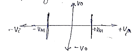
We were doing analog circuits lab for which our instructor asked us to construct a circuit from the transfer characteristics (I have attached the image.) We were working on RC integrators, differentiators, clipping and clamping circuits, and I can't figure what circuit would give a transfer characteristics like this. Could you help me out please?

Also, is fourier transform somehow related to this? I remember me plotting amplitude response of fourier transforms of cos and sin functions, and they looked similar to these transfer characteristics.

\$\endgroup\$
7
  • 2
    \$\begingroup\$ It is not clear to me what your sketch is intended to convey. \$\endgroup\$ Commented Aug 8, 2023 at 11:57
  • \$\begingroup\$ @MathKeepsMeBusy It is the plot of transfer characteristics of some RC circuit. (input voltage on x-axis, output voltage on y-axis) \$\endgroup\$
    – Rach.1961
    Commented Aug 8, 2023 at 12:05
  • 2
    \$\begingroup\$ The figure looks like a two-axis Cartesian plot with two vertical line segments drawn on it. If those line segments represent the locus of your "function", a transfer function it is not. \$\endgroup\$ Commented Aug 8, 2023 at 12:21
  • 1
    \$\begingroup\$ That diagram doesn't make much sense to me. You should talk with your instructor or a TA, so they can figure out what concept you're having trouble with, and clear it up for you. \$\endgroup\$ Commented Aug 8, 2023 at 12:33
  • \$\begingroup\$ What do the Vm lines signify? Shouldn't they be horizontal? What is the circuit gain? \$\endgroup\$
    – Andy aka
    Commented Aug 8, 2023 at 12:34

1 Answer 1

-1
\$\begingroup\$

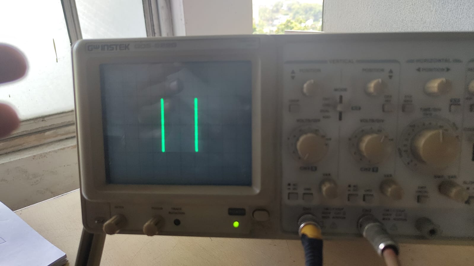
transfer chara Here is the answer: It is the transfer characteristics of a good integrator, when a square wave is applied to the input (i.e., triangular wave is obtained at output. We tried to find the transfer characteristic of integrator circuit today, and obtained this in CRO.

\$\endgroup\$
5
  • 1
    \$\begingroup\$ Could you clarify, is this additional information (in which case, please edit it into your question), or a self-answer? \$\endgroup\$ Commented Aug 9, 2023 at 12:22
  • \$\begingroup\$ @TimWilliams This is the answer to the question I asked. \$\endgroup\$
    – Rach.1961
    Commented Aug 9, 2023 at 13:57
  • \$\begingroup\$ Nope. A transfer characteristic is independent of the input signal. That’s the whole point of calling it a characteristic, vs. “exemplary output response for a square wave”. That’s what caused everyone trouble. Integrators have no fixed transfer characteristic in fact, since their response depends on time. A transfer characteristic is static in terms of time! For an integrator the transfer characteristic must include time, and a graphical way of conveying it would be with a block diagram made up of transfer functions in the s-domain for example. I think your instructor is confusing students. \$\endgroup\$ Commented Aug 9, 2023 at 14:40
  • \$\begingroup\$ In fact, there’s a wild variety of circuits that will have this “transfer characteristic” for any signal, statically, whereas an integrator acts that way only when driven with a square wave. \$\endgroup\$ Commented Aug 9, 2023 at 14:44
  • \$\begingroup\$ @Kubahasn'tforgottenMonica Just today we were told that transfer characteristic is dependent on input signal. It is very confusing, especially since our concepts are not strong. \$\endgroup\$
    – Rach.1961
    Commented Aug 9, 2023 at 17:03

Your Answer

By clicking “Post Your Answer”, you agree to our terms of service and acknowledge you have read our privacy policy.

Not the answer you're looking for? Browse other questions tagged or ask your own question.