0
\$\begingroup\$

I’d like to replace the potentiometer component (RV1) of a typical triac dimmer circuit with a voltage controlled resistor. The DC control voltage has a range of probably about 1 mV - 2.5 V. It seems like there are a couple options for this (namely linear optocouplers and jfets) but they each seem to have their own problems.

I would love to get an opinion on what would be best to use. I’ve attached a picture of a standard triac dimmer circuit in case this isn’t common knowledge.

Edit: I had initially hooked this up with a microcontroller but I want to see if I could do it analog. I have a mic going into a preamp I built and then attached to a full wave rectifier. I'd like to modulate the brightness of the lights in accordance with the amplitude of the audio signal.

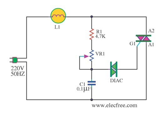
standard triac dimmer circuit

\$\endgroup\$
2
  • \$\begingroup\$ This is an XY problem. If you give us the complete background of what you are trying to accomplish there is probably a better solution. For example, if you have a microcontroller, you would normally do this with a timing circuit. \$\endgroup\$
    – Mattman944
    Commented Aug 22, 2023 at 1:02
  • \$\begingroup\$ I had initially hooked this up with a microcontroller but I want to see if I could do it analog. I have a mic going into a preamp I built and then attached to a full wave rectifier. I'd like to modulate the brightness of the lights in accordance with the amplitude of the audio signal. \$\endgroup\$
    – Eli Y
    Commented Aug 22, 2023 at 1:05

3 Answers 3

0
\$\begingroup\$

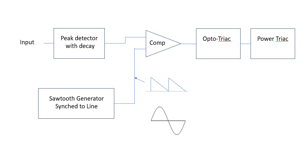
If you are comfortable designing with opamps and comparators, you can do it like this. I made this a long, long, time ago. The sawtooth generator is the only tricky part.

enter image description here

\$\endgroup\$
1
  • \$\begingroup\$ Perfect! Thank you for your help! It's working very well in simulation \$\endgroup\$
    – Eli Y
    Commented Aug 22, 2023 at 2:33
0
\$\begingroup\$

The first advice I'll gave you is be safe! You are working on main voltages, you can hurt you a lot. The second is any device you will place on a main line should be engineered by someone who understand the risk and how to properly size components. Electrical fire do happen!

That being said, here is your answer: Any solid state design won't be isolated. Most commercial design uses this approach with a lot of ISO certifications. Since you are new to electronic, this is an absolute no go in my opinion.

The other approach is with an isolation barrier. But once again, if you don't know what you are doing, I don't want to give you advise on it.

The only approach I could recommend a beginner is to use a solid state relay, that is certified and bought from a reputable brand. It won't do exactly what you want, but at least you have a known good isolation barrier.

Bottom line, main project are not something a beginner should play with.

EDIT: Linear optocoupler are pretty bad (from experience). If you want to couple an audio signal to your light, I would use an isolation amplifier. These have better linearity and performance in general. In that case, I think the isolation barrier is a must. If it connects to other system, keeping it live referenced will be dangerous. There are many circuits that does that. If I remember right, the term you might be looking is Color Organ. A google search should show you several design.

\$\endgroup\$
2
  • \$\begingroup\$ Thanks for the response! I think I may have understated my status. I've worked with mains a few times, but I will continue to heed your warning and be very careful. Can you elaborate on the isolation barrier explanation? I'd like to know if this is feasible for me \$\endgroup\$
    – Eli Y
    Commented Aug 22, 2023 at 1:00
  • \$\begingroup\$ I edited my answer due to the comment top your question. Please add it to que question. \$\endgroup\$
    – Julien
    Commented Aug 22, 2023 at 1:13
0
\$\begingroup\$

If you can light an LED with your signal you could replace the pot with an LDR of adequate voltage and power rating. Physical separation could provide adequate galvanic isolation.

They are made using cadmium (CdS) so you might have trouble sourcing them in more a tightly controlled jurisdiction such as the EU. They are available in the US, China, India with no problem, though many are not rated for adequate voltage for 220VAC mains, or even 120VAC.

\$\endgroup\$

Your Answer

By clicking “Post Your Answer”, you agree to our terms of service and acknowledge you have read our privacy policy.

Not the answer you're looking for? Browse other questions tagged or ask your own question.