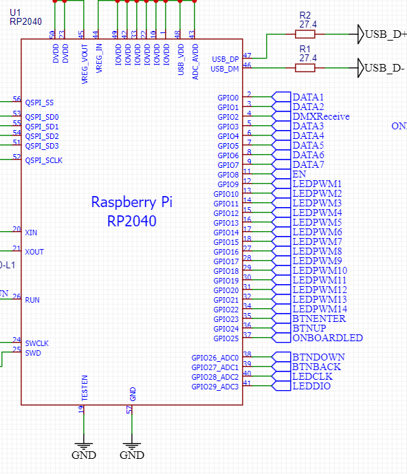
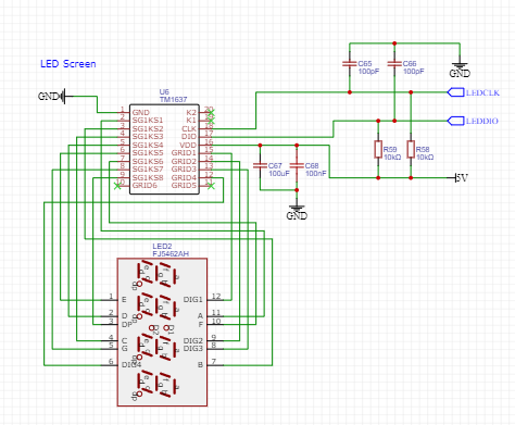
I made my own custom RP2040 board. I'm trying to control a TM1637 chip that is placed on the same board as the RP2040. Before making the main board I did make my own small test board for the TM1637 chip. I hooked it up to a RP Pico, and used pin 2&3. Everything worked as expected.
According to the hardware design guide and datasheet by Raspberry Pi, the RP2040 has 29 GPIO's. But when checking the Pico, GPIO29 does not have a physical pin. So testing that on the Pico is not going to work. Should I not be using GPIO29? According to the datasheet(page 13-14) it should be available for use. And the connections are exactly the same(apart from GPIO's used) as my test setup. I did read somewhere that GPIO29 has a special function for, I believe, voltage sensing for the 3.3 V power for the RP2040. So I don't know if that could be of impact.
I checked with a multimeter for shorts, that came up negative. The TM1637 is receiving the 5 V it needs, ground connections are solid as well.
For more context: I'm on the Arduino platform, and tried the default blink project. That works so the pi is working correctly. When trying the test project for the TM1637 on the pico with external board, it all works fine. The moment I try it on the custom board it stays off.
Sorry if the designs are a little messy, it's a hobby project and I'm not familiar yet with all the design rules.


