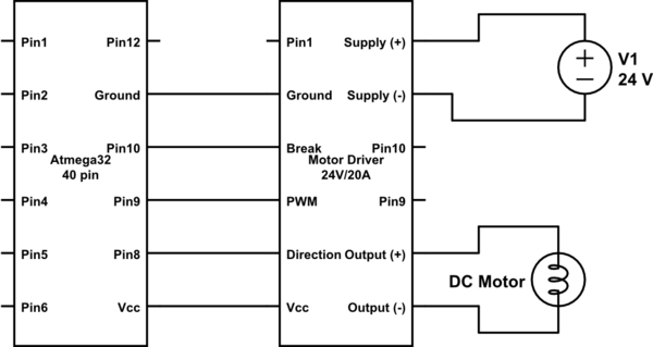
I don't think your motor driver is designed to handle the supply +/- connected but VCC/Ground not connected. You should always have both supplies to the motor driver and the ATMega either ON or OFF, an not have one ON and the other OFF (ATMega ON, driver OFF is probably alright, but you would have to be careful.)
If you require it to function like that, you should take specific measures to allow it to work.
The motor driver should be fully powered or not powered at all at all times. So, instead of using the Vcc/Ground from the ATMega, use a 7805 or the like and generate 5V from the 24V supply. Use this to power the Motor driver's VCC (and NOT the ATMega's VCC)
Once you've split the supplies, you need to translate the logic signals from the ATMega's supply to the Motor Driver's logic supply. Since you're talking about 24V/5A, or over 100W, I'll gather these are fairly heavy duty motors. It's worthwhile to go the extra mile and do this using optocouplers. Optocouplers / optoisolators allow you to translate signals from one supply to the other without any copper / conductive attachment between the two sides. This is useful for a number of reasons, but also tends to expensive. Analog devices has a line of iCoupler isolators which don't use optics but use another method instead. Isolation of this kind (usually identifiable by having separate grounds on both sides, not just separate supplies as in level translating buffers) will make sure that you can run your logic signals from one side to the other without worrying about noise coupling back into your ATMega's ground and supply and all that.
You can avoid proper isolation and use a simpler (and cheaper) level translating buffer like TI's SN74LVC2T45 and family, but you may see strange behaviour come from the high currents that are switching on the motor side.

