12
\$\begingroup\$

Long version

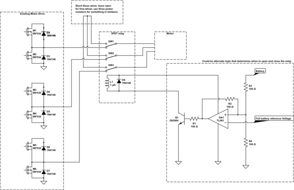
We are using third party motor driver with regenerative braking and a lithium-ion battery. Apparently, this combination is well known in e-bike enthusiasts world as having a huge problem of BMS disconnecting the load while braking with full battery. The driver manufacturer simply pointed out the statement in datasheet that lithium-ion batteries are not supported and we are basically on our own.

While browsing the web I've found many industrial solutions, mostly in VFD context. Nothing small enough to fit into wheelchair. There are also references to chopper circuits for dynamic braking resistors. These are sometimes included into motor drivers with IGBT for external resistor. This seems to be not very good idea unless very high chopping frequency is used to prevent BMS from activation. Another manufacturer suggested a diode with braking resistor. This will, of course, waste the energy and substantially reduce the range.

Short version

Is it possible to create a relatively simple circuit that will limit regeneration voltage by directing part or all current via BJT to dissipate heat on the transistor itself or transistor and resistor combination? The goal is to have it activate only when battery is fully charged and not waste regeneration otherwise.

I am thinking something like a combination of Zener diode, OPAmp, diode, BJT and resistor can do the trick. Not sure if I can come up with a complete circuit on my own, so any advice will be appreciated.

Update

I forgot one important requirement. Because the battery (and hypothetical circuit in discussion) cannot tell the difference between regeneration and charging, the circuit should have additional inhibit input that would disable it while charging. Normally this is done by shorting inhibit pin to the ground, but we do not have an access even to that pin. We might be able to get a signal "charger connected" from the motor controller.

Also here is some additional info asked about in the comments and answers that might help. The battery is 24V 7 cell Li-NCM. We do have an access to BMS configuration, like maximum current, charge and discharge voltage limits etc. Motors are brushed DC, 20A continuous, 40A peak. They have built-in parking brakes disengaged electrically by the controller when power is applied.

Finally, here are some examples of the commercial devices performing this function: from Roboteq and UniDrive. They are expensive, not designed specifically for our application and seem to be permanently out of stock. I was hoping that we can make much simpler device fine-tuned for the job.

Update 2

Many thanks to all participants in the discussion. I'll try to summarize the suggestions below and maybe we can pinpoint the best approach. It seems that all workable solutions can be grouped into the following options:

Option A. Chopper circuit with IGBT or MOSFET controlled by PWM from MCU
I believe, this is how the commercial shunt regulators are made.
Pro: With right gate driver and transistor most of the heat will be dissipated on a brake resistor.
Con: Potentially excessive noise; requires MCU supply; software development time; cost.

Option B. MOSFET controlled by Comparator
While very different from A schematically, I suspect this will behave quite similar to it, with voltage oscillating around threshold voltage, producing chopping effect.
Pro: Simple; heat dissipation on the resistor; cheap.
Con: Could be even noisier than A.

Option C. Linear regulation of the brake resistor current, controlled by over-voltage
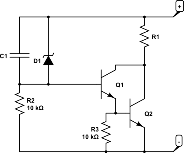
This can be done using OPAmp or BJT pair in Darlington configuration, as suggested by Jasen.
Pro: Reduced EMI; relatively simple;
Con: OPAmp requires either dual supply or biasing; Substantial heat dissipation on BJT requires heatsink; Jasen's circuit might be tricky to adjust for threshold voltage. enter image description here

At this point I am favoring either B or Darlington. What do you think?

Update 3

This question already has an answer, but I just wanted to give a little update to anyone interested.

Winter is here and we've stumbled upon unforeseen problem of BMS switching off charging FET when battery temperature drops under 0 deg. as per cell operational conditions.

So now this circuit is essential not only as a dump for excess regeneration power when battery is fully charged, but as actual braking resistor in cold weather.

\$\endgroup\$
9
  • \$\begingroup\$ Comments have been moved to chat; please do not continue the discussion here. Before posting a comment below this one, please review the purposes of comments. Comments that do not request clarification or suggest improvements usually belong as an answer, on Electrical Engineering Meta, or in Electrical Engineering Chat. Comments continuing discussion may be removed. \$\endgroup\$
    – Voltage Spike
    Commented Sep 13, 2023 at 23:20
  • \$\begingroup\$ @Maple - Did you get a satisfactory answer? I think that the real requirement was not initially clear to most or all respondents (including me). I think I now have a reasonably good idea of what you are trying to achieve, and why. IF you feel that your requirement has not yet been well addressed we could see how we can progress the matter. While it is normally strongly preferred that a question is modified to suit new input and that a duplicate question is NOT generated, that MAY be better in this case. I can explain why. If done the first step would be formulating a complete question. \$\endgroup\$
    – Russell McMahon
    Commented Sep 19, 2023 at 10:11
  • \$\begingroup\$ @RussellMcMahon following your suggestion I've created a new question more focused on specific requirements and actual design. I also accepted Jasen's answer as complete solution, even though yours and Davide's answers were closer to what I am planning to do. \$\endgroup\$
    – Maple
    Commented Oct 1, 2023 at 18:59
  • \$\begingroup\$ @Maple This question never ended up integrating a clear overview of what it was"all about" in the question proper, and the new one just referes back to this one. It is VERY hard for a reader to get a proper idea of what you really want and why. eg wheelchairs get a peripheral mention in paragraph 2. The new question may go the same way as the old without a clear succinct up front overall description. Maybe not, but ... . \$\endgroup\$
    – Russell McMahon
    Commented Oct 2, 2023 at 0:23
  • \$\begingroup\$ @RussellMcMahon I am not sure I can agree with that. The problem of lithium batteries disconnecting themselves is well known and is not specific to wheelchairs. Here is a quote from Onewheel manual: "Never attempt to ride down a long or steep hill with a freshly charged Onewheel. Loss of control or damage to your Onewheel may occur." Pretty much any high power device needs a way to dissipate braking power, even unexpected examples like industrial robots. This is what this question is really about, and 4k views in 3 days shows an interest in the solution. \$\endgroup\$
    – Maple
    Commented Oct 2, 2023 at 3:05

10 Answers 10

11
\$\begingroup\$

this seems entirely possible, when the battery is getting kind of full (as determined by voltage) turn on an extra load until the battery is less full.

if it triggers above the maximum cell voltage it will need to be a fast acting circuit, perhaps something like this:

schematic

simulate this circuit – Schematic created using CircuitLab

Here C1 will activate the transistors during rapid voltage increases and the zener diode will activate during over voltage.

Size the resistor R1 to handle the peak current output of the regenerative braking system, the bottom transistor Q2 will need heatsinking sufficient for 1/4 of the resistors peak output. the trigger voltage will be about 1.3V the cener voltage of zener diode D1

\$\endgroup\$
8
  • 2
    \$\begingroup\$ I think this is the best circuit so far - I think C1 is interesting, but I might leave it out and rely only on the voltage action. I wonder if there might be a better way of reducing the power requirement for the transistor though, 25% is still a pretty huge amount \$\endgroup\$
    – BeB00
    Commented Sep 13, 2023 at 7:12
  • 1
    \$\begingroup\$ You could fix the issue by using an opamp instead of a zener and an N mosfet, giving a sharper switching action - you could probably get it down to 1% power in the transistor, maybe less \$\endgroup\$
    – BeB00
    Commented Sep 13, 2023 at 7:20
  • \$\begingroup\$ Usually you'd use a hysteretic comparator and mosfet. That way, there is essentially no dissipation in the transistor and all of it in the power resistor which is easier to manage. \$\endgroup\$
    – tobalt
    Commented Sep 13, 2023 at 11:09
  • \$\begingroup\$ the poster was worried about slowness, this is the fastest circuit, \$\endgroup\$ Commented Sep 13, 2023 at 14:10
  • \$\begingroup\$ pardon me if it's a stupid idea, but connecting Q1's collector to the + through another resistor (maybe also 10k, low power) would allow Q2's collector voltage to drop further, so R1 dissipates more and Q2 dissipates less? I haven't checked this idea in a simulator \$\endgroup\$ Commented Sep 13, 2023 at 16:19
18
\$\begingroup\$

You have hit upon a well-known problem in Li-ion traction batteries. It the battery is full, it can't receive any more charge, so it disables charging.

The correct solution is to provide both regen and mechanical brakes in the vehicle. If the battery is full, the mechanical brakes are used instead. Also, the mechanical brakes are used at low speed, when regen is less effective (regen cannot hold a vehicle stopped on a hill, for example).

However, I know that some vehicle manufacturer skimp on the mechanical brakes, which is quite dangerous. I have seen it in golf carts, forklifts, and the "GolfBoard" vehicle. The better golfcart manufacturers include a big-ass resistor to absorb the regen energy when the Li-ion battery is full, in addition to mechanical brakes.


To your question: how to build a circuit that absorbs the regen energy when the Li-ion battery is full.

If the BMS has an output signal that is active when charging is disabled, then you use that signal to engage a contactor or MOSFET, which connects the big resistor across the motor controller.

Otherwise, you need to detect that the voltage at the battery input of the controller is excessive, and use that to turn on the contactor. (Detecting the direction of the current would be effective if there were any current, but there isn't because there's nowhere for the current to go). As a detector, you can use a comparator IC (not an Op-amp: that's not what op-amps are for), a voltage reference IC, a resistor divider, either a contactor or a MOSFET, and a high power resistor. For an e-bike, I would use a 500 W resistor: not cheap. I have used toasters as cheap high-power resistors in the past. The problem is that there is a time lag between when the voltage is excessive and the contactor or MOSFET turns on. During that time, the high voltage from regen may destroy the motor controller. To handle that, you can add a high-power transient voltage absorber/suppressor (TVS) that only has to work between when the voltage spikes and the contactor/MOSFET comes on.

\$\endgroup\$
7
  • 1
    \$\begingroup\$ There are no mechanical brakes here, unfortunately, other than parking brakes. And no way to add them or a contactor. We have to rely on voltage level and current direction. \$\endgroup\$
    – Maple
    Commented Sep 12, 2023 at 22:59
  • \$\begingroup\$ The reason I wanted to use OPAmp is to provide dynamically regulated current path, with BJT controlled by the difference between zener and battery voltages. Not an on-off switch as would be the case with comparator and contactor \$\endgroup\$
    – Maple
    Commented Sep 12, 2023 at 23:04
  • \$\begingroup\$ Ah, yes. An Op-amp could help you make a regulated current source. But that would entail dissipating power in a transistor, and a single transistor for 1000 W costs as much as the e-bike. Not a good option at these power levels. \$\endgroup\$ Commented Sep 12, 2023 at 23:07
  • \$\begingroup\$ Would not resistor in series with transistor solve this problem as primary dissipation element? As for the cost, it becomes much less daunting when you think of wheelchair user flying of the chair when BMS cuts off and engages the parking brakes \$\endgroup\$
    – Maple
    Commented Sep 12, 2023 at 23:26
  • 2
    \$\begingroup\$ @DavideAndrea a resistor in series with a transistor gives you all the adjustment you need - an opamp to compare the voltage to a reference and turn on the transistor when the voltage is above that reference is all that's required \$\endgroup\$
    – BeB00
    Commented Sep 13, 2023 at 7:18
6
\$\begingroup\$

Well, let's take something braking down in two seconds from 10m/s of speed with a mass of 150kg (which includes passenger weight, so it would be a rather light wheelchair). That means we need to burn off 3.75kW average over two seconds. You don't burn that amount of power in a semiconductor; you burn it in a device intended for burning off power (or storing it, like a capacitor or a flywheel). The most compact device are brake pads and/or disks. Those can work while sacrificing material and/or keep working while red hot. Resistors tend to be less effective in those categories, but a lot more resilient than semiconductors at similar scale.

\$\endgroup\$
9
  • 3
    \$\begingroup\$ Very valid point. Unfortunately the components used in the chairs are mostly standard and they are not easily convertible for mechanical braking. This is usually done in a controller, which uses regeneration at high speeds and active reverse power at low. \$\endgroup\$
    – Maple
    Commented Sep 12, 2023 at 23:34
  • \$\begingroup\$ I went to suggest the "drain early, drain slow" concept, and found that you were 11 hours ahead of me :-) \$\endgroup\$
    – Russell McMahon
    Commented Sep 13, 2023 at 10:06
  • \$\begingroup\$ At the risk of sound obvious, wheelchairs don't travel at 10m/s (36 kmph (20 mph)). \$\endgroup\$ Commented Sep 13, 2023 at 16:20
  • 1
    \$\begingroup\$ @user253751 These are high-speed wheelchairs designed for people that have places to go, hence, no brakes because they don't stop for anyone. \$\endgroup\$
    – MOSFET
    Commented Sep 13, 2023 at 16:44
  • 2
    \$\begingroup\$ Next question: how can I handle regenerative braking when my traction battery is full and my flywheel is rotating at its maximum rpm? \$\endgroup\$
    – Coxy
    Commented Sep 15, 2023 at 6:14
4
\$\begingroup\$

You can also simply limit the maximum battery charge at the charging station to 90-95% of full charge, in order to have 5-10% as a reserve for braking. Not to mention that avoiding 100% charge is good for battery life as well.

For instance, a 1kWh battery charged to 95% will have 50Wh reserve capacity, enough to absorb the energy of 180kg body going 100m down. That's 1km of constant braking on a 10% downhill slope with no losses.

\$\endgroup\$
5
  • 1
    \$\begingroup\$ "You can also simply limit the maximum battery charge". Yes, this is one option we consider. The third-party electronics we use is a complete system. The only point of access we have is at battery terminals. Typical use scenario is to plug the charger and leave it overnight. We do have a bit of control over BMS settings, but limiting end of charge voltage there also means limiting the cut-off point for regen. \$\endgroup\$
    – Maple
    Commented Sep 13, 2023 at 16:03
  • 1
    \$\begingroup\$ "I would implement an emergency braking by dead shorting the motor". Any loss of power immediately activates mechanical parking brakes. That is the root of the problem, as it leads to rather violent stop. \$\endgroup\$
    – Maple
    Commented Sep 13, 2023 at 16:06
  • \$\begingroup\$ @Maple Yes, this approach will only work if you can reconfigure the BMS every time the charger is plugged / unplugged, not once during production. \$\endgroup\$ Commented Sep 14, 2023 at 8:02
  • \$\begingroup\$ One thing that could work is to detect when the BMS goes into saturation charging mode (the charge current drop rather significantly to about 50% of the normal constant-current charging current) which roughly corresponds to 80-90% of capacity. At this point you could cut the power to BMS. However, it becomes quite complicated to implement, if you consider charge current variations due to cell aging and temperature. \$\endgroup\$ Commented Sep 14, 2023 at 8:08
  • \$\begingroup\$ Another idea is to stop the charging every ~10 minutes, and check the battery voltage at this moment. 90% charge is about 4.1V/cell. If you see voltage above that, you don't resume charging, otherwise you supply voltage to BMS for the next 10 minutes. \$\endgroup\$ Commented Sep 14, 2023 at 8:11
2
\$\begingroup\$

Yes, you can make a circuit that, when the battery is full, redirects power to a brake resistor. You can derive functionality from VFD's where a brake chopper is used to regulate the DC Link voltage, eg: the voltage on positive side of the motor mosfets.
You probably can't do it exactly like that because your battery is your DC-link voltage.

For this you will need two power mosfets, a comparator, and a signal that the battery is full.

One mosfet is in series with the battery (source) to BMS (drain), with the diode pointing to the bms.
When full it disconnects and prevents charging of the battery.
The second mosfet can be a simple n-channel as brake chopper.

The comparator controls the brake chopper and turns it on when voltage on the Battery-BMS mosfet (Vds) becomes positive (eg: bms > battery).

Challenges will be finding a mosfet capable of the current between the battery and BMS, it will also introduce additional losses. There will also be some hardening required to filter the noise generated by the chopper. And depending on the amount of energy you need to take on, it may need cooling on the brake chopper.


The battery switch will also need some boundaries to operate within safe limits, you can't turn it back on before at least discharing some 10 percentage again. In short the BMS vendor is right, this is difficult and requires significant additional effort to make it safe.

\$\endgroup\$
1
  • \$\begingroup\$ Sorry, I don't think we can put mosfet in series with the battery. The controller must be properly powered at all times. \$\endgroup\$
    – Maple
    Commented Sep 13, 2023 at 20:43
1
\$\begingroup\$

So, without worrying about the possible circuits as they have been well explained, you could use an eddy current brake.

Basically an electro-magnet on s spinning disc so that regen current is used to brake the vehicle. Many applications use them so lots of examples exist.

\$\endgroup\$
3
  • \$\begingroup\$ This is a good idea in general (and with a smart enough circuit the electromagnet can even be powered by drawing power off the motor :) ) but I understand the asker wants a controlled deceleration profile managed by their motor driver. \$\endgroup\$ Commented Sep 13, 2023 at 16:23
  • \$\begingroup\$ @user253751 I'm not sure I saw that requirement in the question or in OPs comments \$\endgroup\$
    – BeB00
    Commented Sep 13, 2023 at 17:09
  • 1
    \$\begingroup\$ @user253751 "but I understand the asker wants a controlled deceleration profile managed by their motor driver" That is correct. It is a reason why we cannot insert anything between the controller and motors or disconnect the battery from the controller. About the only thing we can do is redirect excess current around the battery. \$\endgroup\$
    – Maple
    Commented Sep 13, 2023 at 19:16
1
\$\begingroup\$

This complements (and overlaps) other answers:

Energy will be wasted at any time that it is dissipated rather than used for regenerative charging. This applies whether braking is mechanical, or dissipated in an external resistor or in the motors.

@User107063's and Dmitry's answers (and others) of reducing battery state of charge to allow burst of regenerative braking, PLUS using a PWM modulated resistive load to bleed off battery capacity to provide a reserve for regenerative energy absorbtion, will do what you want.

The PWM on/off ratio can be very easily varied to provide a variable factor of N x the resistor used. eg a 10 Ohm resistor with 1:3 PWM (25% on) is the equivalent of a 40 Ohm resistor. The switch (probably a MOSFET can be hard on or fully off and dissipate almost zero power. The battery state of charge must be kept below the point where it can absorb a maximum braking burst. The dissipating resistor needs to be able to dissipate ALL the average braking energy over a period of operation.

Shorting the motors will dissipate the energy IN the motors.

PWM shorting the motors will vary the braking power (and force).

Driving the motors actively against the direction of actual or potential motion will provide low speed braking and static holding.

Overall, not having any mechanical brake is not a marvellous idea.

The battery needs to be capable of absorbing regenerative energy at a rate that does not exceed it's specified charge current. eg a 120 kg total load descending Dmitry's suggested 10% slope at say 2 m/s (7 km/h) will dissipate mgv x 10% = 240 j/s (ie 240 watts power.) That's probably well within typical LiPo battery spec.
A rapid stop will be similar.

A 500 watt resistor is not overly physically large and may prove an attractive alternative. I used to test exercise bikes controllwers that I designed, with a maximum required dissipation of 500 Watts continuous. A fully aircooled (no fan needed) air-wound Nichrome wire coil did the job well,

\$\endgroup\$
7
  • \$\begingroup\$ If you use PWM, wont the voltage during the off time rise to a level that breaks everything? With 100uF of capacitance, if you had to do 3.75kW the voltage fluctuation during your PWM would be many tens of volts. You could go faster, but then your transistor switching losses add up, and if you're using a transistor beefy enough to switch hundreds of amps, it's going to have a lot of gate capacitance. You could add more line capacitance, but it's a whole lot easier to just not use PWM (not to mention the electrical noise it will generate, I can't imagine the FCC would be very happy) \$\endgroup\$
    – BeB00
    Commented Sep 13, 2023 at 17:05
  • \$\begingroup\$ (previous calculations assuming 25kHz PWM, going faster heats up more etc) \$\endgroup\$
    – BeB00
    Commented Sep 13, 2023 at 17:38
  • \$\begingroup\$ @BeB00 "I can't imagine the FCC would be very happy" nice to meet someone who knows the pitfalls :) \$\endgroup\$
    – Maple
    Commented Sep 13, 2023 at 19:10
  • \$\begingroup\$ @Maple In my exercise bike load controller I was only switching an up to 500 watt load. From memory (20+ years ago) PWM frame rate was 20 or 25 kHz. (Aim was inaudibility while being as low as otherwise possible. The equipment was manufactured in Taiwan but had to pass EMI testing for sale in the US (and did). \$\endgroup\$
    – Russell McMahon
    Commented Sep 14, 2023 at 8:44
  • \$\begingroup\$ @BeB00 See my above comment to Maple. The 3.75 kW figure came from user107063's 10 m/s (36 km/h) stop in 2 seconds = 0.5g. - In my calulations above I used 2 m/s (7.2 km/h) and slightly different assumptions for only 240 watts. I think 500 watts would be usful enough in many cases. For better figures the OP needs to better define the requirement. || PWM is just to allow variable braking rate. The resistor needs to have rated wattage to dissipate maximum power for as long as the design requires. \$\endgroup\$
    – Russell McMahon
    Commented Sep 14, 2023 at 8:58
0
\$\begingroup\$

(First time using the schematic editor, so disregard all values; I just left the defaults.)

You can usually use the motor itself to absorb the energy - the stator could handle short-term loading while shorted. You might have to check with your motor supplier. I've used this technique in the past, but I had access to the internal workings of the output bridge (inverter of the drive) and could use the IGBTs to short or "chop" the current in firmware. I suggest using a contactor if you don't have that luxury.

As a compromise, you can use power resistors to burn the excess energy. The value depends on how much heating your motor can handle during brake mode - lower value resistors = more aggressive braking. The limit, of course, would be a complete short.

schematic

simulate this circuit – Schematic created using CircuitLab

\$\endgroup\$
9
  • 1
    \$\begingroup\$ heating up the motor itself seems like a bad idea - surely the decreased lifetime of the motor will cost more than an appropriately sized resistor? \$\endgroup\$
    – BeB00
    Commented Sep 13, 2023 at 7:13
  • \$\begingroup\$ @BeB00 Only if the expected lifetime decrease is significant. Resistors in kW range are not that cheap (or small) so if you need a resistor which costs 1/10 of the price of a motor, reducing motor lifetime by 10% is actually more economical. Especially if such braking is exceptional (can only happen if you go downhill directly after a full charge). \$\endgroup\$ Commented Sep 13, 2023 at 9:04
  • 1
    \$\begingroup\$ Shorting the stator without any electric load will just push out the electric field from the rotor. You may get a ratcheting effect but it will put back almost as much energy as it takes out. To take out significant energy, you'll need more than just the stator resistance to work against as it is not well-matched to the generator impedance (if it were, the motor would heat up like silly under normal operating conditions). \$\endgroup\$
    – user107063
    Commented Sep 13, 2023 at 12:44
  • \$\begingroup\$ The right side of this schematic is exactly the detection circuit I had in mind. However we cannot switch the motor wires. The braking must be fully controllable (both speed and deceleration), and that is the function of the motor drive module. \$\endgroup\$
    – Maple
    Commented Sep 13, 2023 at 16:14
  • \$\begingroup\$ @Maple OK. If you don't have access to the internals of the OTS motor driver (VFD), Just use 3 external mosfets (lower half of the inverting bridge) and bang-bang the gate drives, in sync, with hysteresis sens circuitry thresholder at say 24V-26V. You leave the drive connected to the motor. The output of the drive has to be off (high-impendence) during the over-voltage case or you short the drive outputs. \$\endgroup\$
    – MOSFET
    Commented Sep 13, 2023 at 16:32
0
\$\begingroup\$

There's an interesting electric-hybrid truck company building a prototype, and documenting it on youtube.

Edison Motors in Canada describes it in

https://www.youtube.com/shorts/EJJj_aTvg7g

In this short they mentioned using an air-cooled resistor bank for electric braking, and then realising their generator can also work as an electric motor, so backfeeding to the diesel means they can use a "jake brake" or against engine compression.

Elsewhere he has bemoaned that they couldn't use a high voltage Jacob's Ladder electric arc to discard the extra energy to the sky - that could be spectacular.

Another place to "dump" excess energy is into water via a heating element, but water is heavy and when that boils you can't keep adding heat.

\$\endgroup\$
2
  • 1
    \$\begingroup\$ Just for interst: Water absorbs 850 litre.degrees-C per kWh. So about 10 litre per kWh heated from 20 to 100C. Then it cools as fast as you can manage :-). \$\endgroup\$
    – Russell McMahon
    Commented Sep 14, 2023 at 9:02
  • \$\begingroup\$ @RussellMcMahon excellent point - there's also a weight cost. One might use the radiator water, but that shouldn't be allowed to spike in temperature, and its probably ~110 degrees C under pressure already. Some diesels use water injection but again that's a hybrid with a generator design. Maybe a dedicated bank of super-capacitors which are always left discharged until the regen brakes are needed AND the main battery is topped off, but discharging that slowly+usefully might be a challenge. \$\endgroup\$
    – Criggie
    Commented Sep 14, 2023 at 9:59
0
\$\begingroup\$

Is it possible to create a relatively simple circuit that will limit regeneration voltage by directing part or all current via BJT to dissipate heat on the transistor itself or transistor and resistor combination? The goal is to have it activate only when battery is fully charged and not waste regeneration otherwise.

Let me try again.

You have not provided a schematic of how the system works at present. Nor do we know the model of the motor controller, the Battery Mangagment System, or the battery (which might or might not have it's own integrated electronics). As a result, answers will involve guesses, assumptions, and speculation. Reticence is not the way to get the best answers.

The EMF generated by a permanent magnet DC motor depends upon the rotational speed of the motor. If the EMF generated by a motor is used to charge a battery, either there must be some mechanism to boost the voltage from the motor to that of the battery, or the rotor speed of the motor must be high enough to generate that voltage directly.

The OP has stated in comments, that, as far as they know, there is no hidden boost converter, and that the battery is recharged directly with the voltage supplied by the motor.

From this we conclude that regerative braking in this vehicle occurs only when the motor rotor speed, and consequently the vehicle itself are going fast enough. That is, there is a vehicle speed, below which regenerative braking does not work. Furthermore, that speed is not insignificant. It is generally not attainable with an open "throttle" on level ground. That is a consequence of the EMF generated by a motor at a given speed will be less than the applied voltage (i.e. the battery) needed to reach that speed, (on level ground). But, to charge the battery, the EMF needs to be at least the battery voltage.

So, if the wheelchair does not brake regeneratively, pushing current into the battery at "lower" or "normal" speeds, how does it brake?. The OP informs us that there are no mechanical brakes other than a "parking" brake, which causes an undesirably sudden stop if engaged while the vehicle is in motion.

It appears that the wheelchair does not yet have a resistive brake. That is, a brake that uses the EMF of the motor to drive a current through a resistor or some similar dissipative load.

So how does the wheelchair brake normally? Unlike bicycles, most personal mobility vehicles can be powered in reverse. For that purpose, they generally have an H-bridge motor drive. If the actual speed is less than the commanded speed, voltage is applied to the motor one way. If the actual speed is greater than the commanded speed, voltage is applied to the motor the other way.

Slowing down a motor (aka braking) by applying power to the motor which creates a torque in the opposite direction that the rotor is turning is called plug braking. That is probably the method the motor controller uses when the motor's rotor is spinning below the speed necessary to charge the battery.

Plug braking causes high currents to flow through both the battery and the motor. Lead acid batteries are generally fine with very high currents. However a BMS for a Lithium ion battery may well decide the battery is drawing too much current and disconnect the battery. That is one possibility that must be addressed when substituting lithium batteries for lead acid.

The current drawn from the battery during plug braking may not be continuous. It may be pulsed in the H-bridge. However, even if the average current drawn might be within the safe range for a Lithium ion battery, the BMS may still decide that the peak currents are not.

Does the wheelchair brake "normally" when it's velocity is below regenerative braking speed? Does it disconnect the battery if the speed command is brought too quickly to zero? We don't know, but it would be good if the OP could inform us.

That brings us to an interesting question. If the motor controller uses plug braking at "normal" speeds, and regenerative braking at high speeds, it there an a way to disable such a transition? If so, we could use plug braking when the the battery is full or the velocity low, and regenerative braking when the battery is not full, and the velocity is sufficient for regenerative braking. But, alas, we know nothing about the motor controller, so we don't know if implementing such a scheme is feasible.

In a previous version of this answer, I proposed using chopper controlled resistive braking using a resistor rated for high power and a MOSFET. However, if the hypothesis that your motor controller uses plug braking at speeds below those sufficient for regenerative braking is true, we must ask whether the motor controller and the resistive braking system would play nicely together.

If the OP would kindly provide more information about the motor controller, couch as its manufacturer, its model, and datasheet if available, and likewise for the BMS and battery, we can perhaps resolve some of these issues.

\$\endgroup\$
13
  • \$\begingroup\$ If you have a microcontroller, you don't need any PWM - turning the transistor fully on for the duration of the braking is sufficient. When OP talks about regulation I assume they are talking about regulating with current path is taken (battery vs resistor) \$\endgroup\$
    – BeB00
    Commented Sep 13, 2023 at 7:15
  • \$\begingroup\$ @BeB00 "I assume they are talking about regulating with current path is taken (battery vs resistor)" Yes, exactly. The idea is to have a parallel (to the battery) path for regen current, that would bleed the excess energy if the battery is full, allowing the battery to be recharged otherwise. \$\endgroup\$
    – Maple
    Commented Sep 13, 2023 at 16:20
  • \$\begingroup\$ @MathKeepsMeBusy The resistor in series with transistor (or IGBT) is how I envisioned the solution and I said as much in the question. I also mentioned my concern about any PWM-based approach, because any chopping means at least part of the time the full voltage is allowed to pass through. Could be enough for BMS to trigger, unless the frequency is very high. We already have two MCUs in our own part of the system (seating and safety control) so that would not be a problem. I just hoped for simple pure analog solution. \$\endgroup\$
    – Maple
    Commented Sep 13, 2023 at 16:30
  • \$\begingroup\$ @Maple right, in which case they wouldn't need PWM, they would just turn the transistor fully on (as opposed to specifically regulating it in some way with PWM) \$\endgroup\$
    – BeB00
    Commented Sep 13, 2023 at 16:52
  • 1
    \$\begingroup\$ @MathKeepsMeBusy I believe your edited answer has a lot of wrong premises. First, I am not trying to limit EMF voltage on the motor. I am trying to limit a voltage on battery terminals to prevent BMS from disconnecting. Second, any sufficiently low resistance across battery terminals will limit battery voltage. The rest of EMF will be split between motor windings, wires and bridge FETs. \$\endgroup\$
    – Maple
    Commented Sep 13, 2023 at 19:04

Your Answer

By clicking “Post Your Answer”, you agree to our terms of service and acknowledge you have read our privacy policy.

Not the answer you're looking for? Browse other questions tagged or ask your own question.