2
\$\begingroup\$

I am on a college project where we make F1 style cars for competitions. Ours is an electric car using a 588 V(maximum) battery to drive the motor.

The inverter has a capacitance that, by the competition rules, we need to discharge when we shutdown the car. For this, we use a 4.7 kΩ power resistor.

I'm in charge of designing the discharge circuit, in which I have an input that indicates when I want to discharge the capacitor. When the input is 0 V, the discharging circuit should be closed so when the car turns off (or fails) it should be discharging. When I have 12 V, the car is ready to drive and the discharging circuit should be opened.

Right now I'm trying to select the component which will switch the circuit ON and OFF.

My options are:

  • Use an N channel depletion MOSFET: I don't know how to implement it as I will need a negative Vgs to turn it OFF.
  • P channel enrichment MOSFET: There doesn't seem to be many in the market that supports that voltage.
  • IGBT: they are normally OFF, so I don't think I can use it.
  • Relays: I can't find any that are NC and support that voltage either.

Any ideas?

\$\endgroup\$
5
  • 3
    \$\begingroup\$ What happens in that space of time when the voltage is between 0 volts and 12 volts. You need to think about hysteresis and preventing serious failure. \$\endgroup\$
    – Andy aka
    Commented Sep 15, 2023 at 11:58
  • \$\begingroup\$ Re, "can't find any [relay] that...support that voltage." Can you cheat? What do you suppose will be the greatest voltage that ever appears across the relay contacts at the moment when the contacts open? Can the power-up sequence be planned such that the relay never has to interrupt the full 588 Volts? \$\endgroup\$ Commented Sep 15, 2023 at 12:52
  • \$\begingroup\$ Hey @Andyaka the 12V comes directly from a 12V battery so I don't think I will have any problems about that \$\endgroup\$ Commented Sep 15, 2023 at 13:34
  • \$\begingroup\$ @SolomonSlow the maximum battery voltage is 588V so that's the maximum voltage that the capacitor will be charged at. And no, I don't think we can change the power-up sequence as It would mean to change too many things that are already done \$\endgroup\$ Commented Sep 15, 2023 at 13:41
  • 2
    \$\begingroup\$ @GabrielCorrales, Voltage matters most for a relay when the contacts open because that's when an arc is started that must be extinguished in order to interrupt the circuit. But your relay contacts only ever open during power-up, so I was wondering if they might do that before seeing the full system voltage. They will see the full 588V on closure, but that might not matter as much because any arc will be fully extinguished by the time the contacts are closed, and arc current is limited by the resistor. \$\endgroup\$ Commented Sep 15, 2023 at 14:35

4 Answers 4

4
\$\begingroup\$

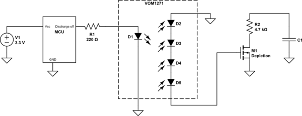
For a passively on or default on circuit requirement, this is how I would do it:

schematic

simulate this circuit – Schematic created using CircuitLab

As you state, you need negative voltage to turn off a depletion MOSFET. Cheat with a photovoltaic driver, for example VOM1271, "upside down".

Depletion MOSFETs are available with over 1 kV voltage rating, for example from IXYS.

\$\endgroup\$
2
  • \$\begingroup\$ That seems pretty promising. However, It seems to generate a voltaje of about 8.5V. The N channel depletion MOSFET I've got needs a Vgs voltage between -2.5 and -4.5V. How would I get rid of those remaining ~6V ? \$\endgroup\$ Commented Sep 15, 2023 at 16:59
  • 2
    \$\begingroup\$ @GabrielCorrales That’s minimum Vgsth. You can drive it with -12 V if you want. \$\endgroup\$
    – winny
    Commented Sep 15, 2023 at 17:22
15
\$\begingroup\$

Forgive me for addressing the problem instead of your intended solution.

A 4.7 kOhm power resistor draws negligible power compared to the motor driver (70 W vs ~ 20 kW peak), and does so only when the ignition is on. Therefore, it's perfectly reasonable to leave it in place across the motor driver DC input at all times, especially in a one-off vehicle that will be disassembled after the race. No need to switch the resistor on only when the ignition is turned off.

Much easier.

But, if you really must turn off the resistor, then place it in series with the normally-closed contacts of a relay whose coil is powered by the 12 V ignition voltage. Whenever the ignition is off the relay contacts are on and the resistor is across the DC input of the motor driver.

EDIT: Here are a few reed relays with 12 V coil and high-voltage N.C. contacts

Much easier.

\$\endgroup\$
4
  • 1
    \$\begingroup\$ The OP did say that he can't find a relay with sufficient voltage rating on the contacts. \$\endgroup\$
    – Dave Tweed
    Commented Sep 15, 2023 at 12:07
  • 1
    \$\begingroup\$ @DaveTweed A kilovac ought to be suitable, if the price isn't a dealbreaker. \$\endgroup\$
    – Hearth
    Commented Sep 15, 2023 at 12:16
  • \$\begingroup\$ @DaveTweed. I added a link to 28 reed relays that will work for OP. \$\endgroup\$ Commented Sep 15, 2023 at 13:05
  • 2
    \$\begingroup\$ Thank you very much. I already gave the idea of keeping the resistor connected but people weren't too amused about that. I will keep insisting though \$\endgroup\$ Commented Sep 15, 2023 at 13:51
3
\$\begingroup\$

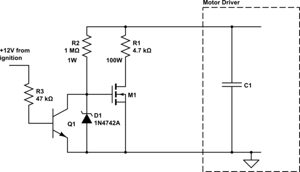
I don't see the problem with using a "normally off" device like an enhancement-mode NMOS transistor. You just need to bias the gate from the capacitor, and short it out when you want the bleed resistor turned off.

schematic

simulate this circuit – Schematic created using CircuitLab

\$\endgroup\$
4
  • 1
    \$\begingroup\$ yeah that's how it was previously done but by the competition rules, the discharge circuit needs to be fail-safe so that it discharges when the power is out. \$\endgroup\$ Commented Sep 15, 2023 at 13:58
  • 4
    \$\begingroup\$ The design will discharge when 12V is not present. It uses the voltage present at the capacitors you're discharging to keep the FET on (R2 is a pull-up). There's two concerns I would have, though: you probably don't have a common ground between the 12V system and the HVDC system, so Q1 should be an optocoupler. And it won't discharge the capacitors below the Vgs(th) of M1, roughly 3-5V - this is probably fine. \$\endgroup\$ Commented Sep 15, 2023 at 21:16
  • 1
    \$\begingroup\$ Using 2x resistors in parallel for R2 is probably a good idea in case either fails open circuit. You may also need two or more in series for voltage rating. \$\endgroup\$ Commented Sep 15, 2023 at 21:17
  • \$\begingroup\$ This circuit is “normally on” because it biases the gate from the capacitor voltage and is a good option. \$\endgroup\$
    – asdf30
    Commented Sep 18, 2023 at 2:36
3
\$\begingroup\$

Use an N channel depletion MOSFET: I don't know how to implement it as I will need a negative Vgs to turn it OFF.

I have previously used a normally-on transistor switch in a 1300 V impulse generator I built with great success. The working voltage is much higher, but the design is potentially a useful solution to similar problems like this one as well.

In that project, the high-voltage capacitor bank must be immediately discharged when the control voltage is lost. I considered the use of a bleeding resistor, but rejected the idea as it would increase the quiescent current significantly, forcing the use of a more powerful high-voltage supply than necessary. I also considered the use of a mechanical relay but didn't use it due to concerns of finding one with a suitable rating and the additional board space required.

Negative Gate Bias Generation

If the required negative bias is not lower than -5 V, it can easily be generated using the classic and inexpensive LM2776 charge pump chip to build a rail inverter with just two capacitors, and it's directly controllable from a microcontroller using its ENABLE pin.
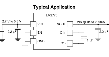
LM2776 Charge Pump IC

If the required negative bias is lower than -5 V (or high-voltage SiC JFETs, the gate voltage can be as high as -20 V). One can use a DC/DC converter as general-purpose DC/DC ICs are also widely available by multiple chipmakers, use the search engines. Three topologies are possible:

  1. Buck-boost converter

    The standard solution.

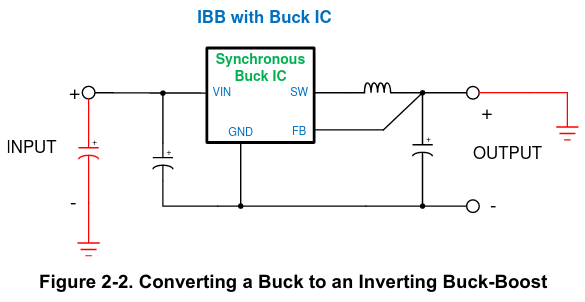
  2. Buck converter

    Using a buck converter as a inverting buck-boost converter

    Ordinary buck converters for positive supply can "abused" as an inverting buck-boost converter by connecting it in a way that moves the ground reference. See TI application note: Working With Inverting Buck-Boost Converters. A limiting factor is the voltage rating of the buck converter, which is the distance between the positive and negative voltage.

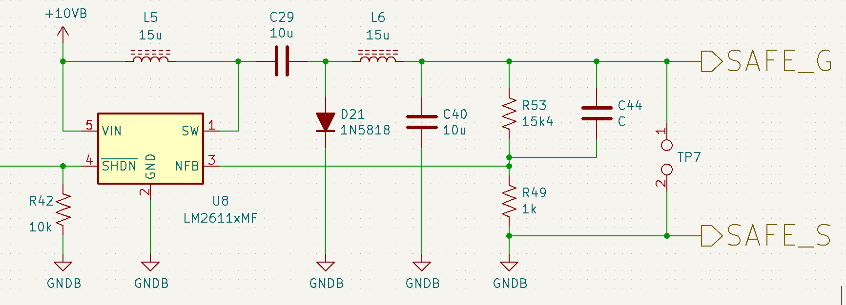
  3. Cuk converter

    LM2611 Cuk converter

    This is the solution I used, based on the LM2611 controller. Input is 10 V. Output is -20 V. This is arguably overkill as it requires two inductors and provides no value other than generating a negative bias. But the inherent capacitive DC isolation is a plus - in case the transistor fails with a short circuit, no DC current flows. When combined with a capacitor with a high-voltage rating and a clamp at its output pin, it can also prevent high-voltage from backfeeding into the controller in case of a fault.

To guarantee an eventual discharge when the control voltage is completely lost, the ENABLE pin is set to low by default using a pull-down resistor, and the negative output also has a bleeding resistor. Furthermore, the microcontroller output is high-impedance upon reset, with the brown-out detector enabled is fused, so a slight voltage drop (due to power disconnection) would also immediately reset the microcontroller, discharging the capacitor bank earlier than a "passive" discharge.

DC/DC converters lack galvanic isolation, but the ENABLE pin can be paired with an external one. In my project, the high-voltage side is controlled by a separate microcontroller, isolated from the low-voltage side with a pre-existing galvanic isolation barrier, so the destruction of the microcontroller is not an issue. However, in most designs with only a single microcontroller, optical isolation is strongly recommended. Photovoltaic driver like VOM1271 as recommended by winny can be a great choice for this use case, hitting two birds with one stone (on the other hand, a DC/DC converter is much easier to find than a photovoltaic driver).

Transistor Selection

Suitable normally-on transistors for high-voltage applications not that common, but useful specialties do certainly exist on the market. For exmaple, IXYS (now Littelfuse) offers N-Channal Depletion Mode MOSFET from 100 V to 1700 V.

High-voltage JFETs using Silicon Carbide (SiC) are also new promising solution. (Who knows people are still making new JFETs these days? Wide-bandgap semiconductor is a game changer.) Like depletion-mode MOSFETs, they're normally-on. UnitedSiC (now Qorvo) has plenty of special HV normally-on JFETs from 1200 V to 1700 V.

Speaking of price. So far, the cheapest part I know is UF3N170400B7S (1700 V, 400mΩ, 5A), they cost only $9 on Digikey and Mouser, presumably due to its non-standard SMD package and low demand. UnitedSiC's 1200 V parts are more expensive, currently sold at $15, an 1.5x expense. The HV depletion MOSFET offerings by the competition from IXYS/Littelfuse are also currently more expensive than this part.

Beware that these high-voltage JFETs switches often have an integrated MOSFET in series to overcome its normally-on "problem" to make a normally-off switch. Read the datasheet to make sure you're buying the normally-on raw JFET. Another potentially confusing aspect of the special UF3N170400B7S is that it has four terminals. There's an extra terminal called "KS". It probably means "Kelvin Source", which is physically the same thing as the "Source". It's just an extra path, meant to be connected straightly to the driver output rather than the common ground plane/rail. This avoids corrupting the driving signal due to ground bounce at the "Source" while a high current is being switched by the FET.

\$\endgroup\$
2
  • \$\begingroup\$ Wow!! Thank you very much. I learned a lot. I will surely go with the photovoltaic driver. The only problem I have is that the output is 8V, while the Vsg voltage ranges between 3.5 and 4.5V. I guess I can fix it with a resistor and a Zener, can't I? \$\endgroup\$ Commented Sep 17, 2023 at 10:45
  • 1
    \$\begingroup\$ @GabrielCorrales What is the part number of your FET? Often, the Vsg given in the summary (and even some curves) are lower than what they can safely withstand. Vendors do this for marketing reason, because people usually want low gate voltage. You can examine the full datasheet for all references of Vgs. Do you see any parameter tested under a higher voltage? If so, it's probably safe. For example, in the datasheet of IXTY08N100D2, the Vgs curve is only given at -4.5 V. But Vgsx (Continuous) is actually -20 V, and in fact some parameters such as capacitance are tested with Vgs = -10 V. \$\endgroup\$ Commented Sep 17, 2023 at 12:03

Your Answer

By clicking “Post Your Answer”, you agree to our terms of service and acknowledge you have read our privacy policy.

Not the answer you're looking for? Browse other questions tagged or ask your own question.